


Brushless direct current motor (BLDC) and its main driving mode
Time:2024-06-05
Views:70
I. Overview
1.1 BLDC and its components
The brushless DC motor uses electronic commutator to replace the mechanical commutator of the traditional DC motor, thus overcoming a series of disadvantages such as noise, spark, electromagnetic interference and short life caused by the brush and commutator. This type of motor has a series of advantages such as AC motor simple structure, reliable operation, easy maintenance, and DC motor high operating efficiency, no excitation loss and good speed regulation performance, and is more and more widely used in the industrial field, typical applications include but are not limited to: Household appliances, power tools, electric bicycles, electric motorcycles, electric balancing vehicles and other fields.
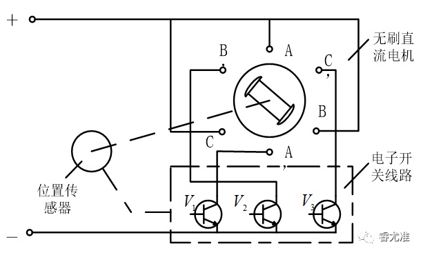
Figure 1-1 Components of a brushless DC motor
The composition of the brushless DC motor is shown in Figure 1-1, which mainly includes the motor body, position sensor and electronic switching circuit.
● The motor body is similar to the permanent magnet synchronous motor in structure;
● The electronic switching circuit is composed of two parts: power logic switching unit (such as IGBT, MOS tube, etc.) and position sensor signal processing unit;
● The switching sequence of the electronic switching circuit is synchronized with the rotation Angle of the rotor, which plays the reversing role of the mechanical commutator.
1.2 Working principle of BLDC
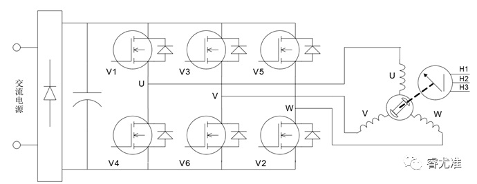
Figure 1-2 Schematic diagram of the BLDC control principle
The control diagram of the brushless DC motor is shown in Figure 1-2. The main circuit is a typical voltage-type AC-DC-AC circuit. The inverter provides symmetrical alternating rectangular waves of constant amplitude and constant frequency 5-24KHz modulated waves.
The N-S alternating exchange of permanent magnets causes the position sensor to generate H3, H2 and H1 square waves with a phase difference of 120〫, thus producing an effective six-state coded signal: 010, 011, 001, 101, 100, 110, through the logic component processing to generate V6-V1 conduction, V5-V6 conduction, V4-V5 conduction, V3-V4 conduction, V2-V3 conduction, V1-V2 conduction, That is to say, the DC bus voltage is successively added to U->V, W->V, W->U, V->U, V->U ->W, so that each pair of N-S poles turned by the rotor, V1, V2, V3, V4, V5, V6 power tubes are fixed into six states in turn, as shown in Figure 1-3.
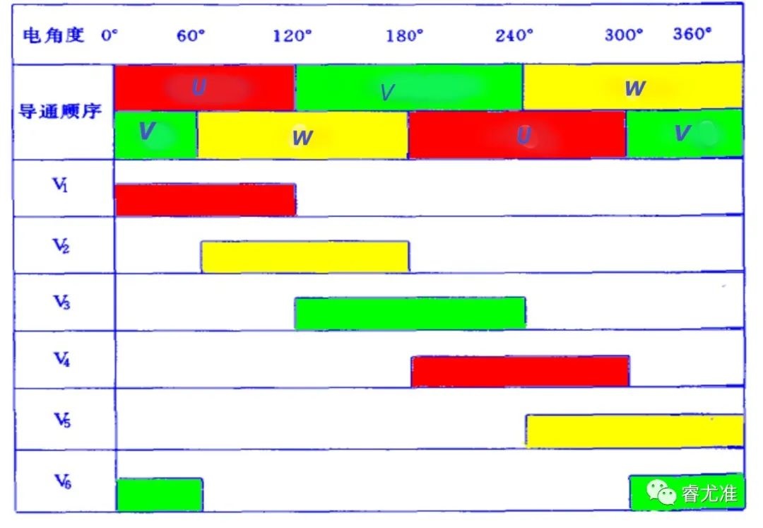
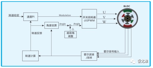
Figure 1-3 Two-phase conduction sequence table of winding and MOS tube in star-shaped three-phase six-state
The magnetic field axis generated by the stator winding rotates 60〫 electrical Angle in space, and the rotor rotates according to the stator magnetic field equivalent to 60〫 electrical Angle spatial position. When the rotor is in the new position, the position sensors U, V and W generate a new set of codes according to the convention, and the new codes change the on-on combination of the power tube. The magnetic field axis generated by the stator winding is further advanced by 60〫 electrical angles. In this cycle, the brushless DC motor will produce continuous torque, dragging the load for continuous rotation.
Second, the mainstream driving way of BLDC
At present, there are three main driving methods for BLDC: square wave control (also known as trapezoidal wave control, 120° control or 6-step commutation control), sine wave control and FOC control (also known as vector conversion, magnetic field vector directional control).
2.1 Square wave control
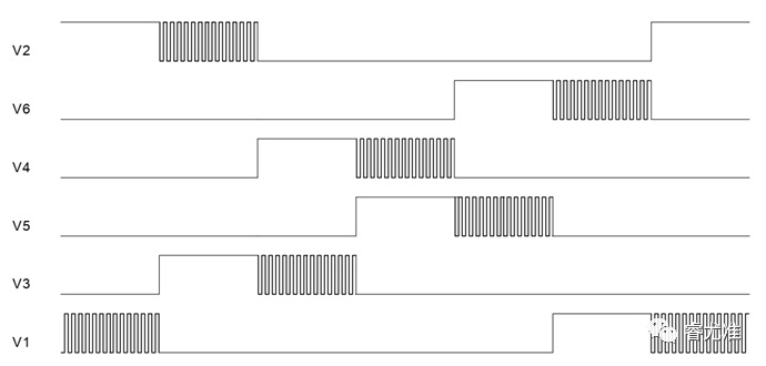
Figure 2-1 Basic principle of six-step square wave commutation control
The basic principle (see Figure 2-1) :
● Use Hall sensor or non-inductive estimation algorithm to obtain the position of the motor rotor;
● According to the position of the rotor in 360° electrical cycle, 6 commutation every 60° commutation;
● Each reversing position of the motor output a specific direction of the force;
● The phase current waveform of the motor is close to square wave, so it is called square wave control.
Advantages: The control algorithm is simple, the hardware cost is low, the use of ordinary performance of the controller can obtain a higher motor speed;
Disadvantages: torque fluctuation, there is a certain current noise, efficiency can not reach the maximum.
Application scenario: It is suitable for occasions where the rotation performance of the motor is not required.
2.2 Sine wave control
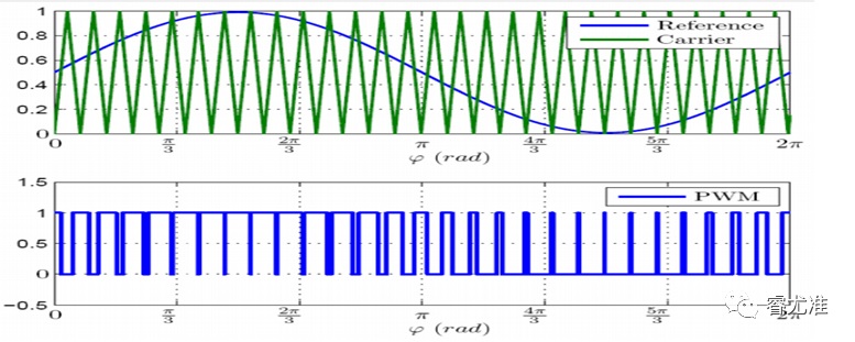
Figure 2-2 Basic principle of BLDC sine wave control
The basic principle is shown in Figure 2-2. The details are as follows:
● Apply SVPWM wave, output 3-phase sine wave voltage to the motor winding;
● The motor winding generates sine-wave current;
●control the amplitude and phase of the sine wave current to achieve the purpose of controlling the motor torque;
●There is no concept of square wave controlled commutation, and it can be considered that an infinite number of commutations are carried out in an electrical cycle.
Advantages: torque fluctuation is small, current harmonics are less, no commutation current mutation, motor running noise is small;
Disadvantages: The performance requirements of the controller are high, and the motor efficiency can not be played to the maximum.
Application scenario: where the motor operation noise is required to be high.
2.3 FOC control
The FOC control mode can be regarded as the upgraded version of sine wave control, which realizes the current vector control, that is, the vector control of the stator magnetic field of the motor.
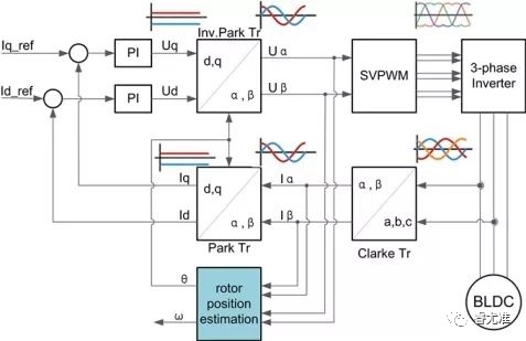
Figure 2-3 Basic principles of FOC control
Figure 2-3 shows the basic principle, which is described as follows:
●The sine-wave stator current is decomposed into parallel to the magnetic field magnetic field component current and perpendicular to the magnetic field torque component current;
● Control the two currents respectively;
The complete decoupling of magneto-current component and torque current component is realized.
Advantages: low torque fluctuation, high efficiency, low noise, fast dynamic response;
Disadvantages: high hardware cost, high requirements for controller performance, motor parameters need to be matched.
Third, which way is more suitable for future development?
At present, FOC is the best choice for efficient control of brushless direct current motor (BLDC). It can precisely control the size and direction of the magnetic field, making the motor torque stable, low noise, high efficiency, and high speed dynamic response. At present, it has gradually replaced the traditional control method in many applications, and has attracted much attention in the motion control industry.
|
Disclaimer: This article is transferred from other platforms and does not represent the views and positions of this site. If there is any infringement or objection, please contact us to delete it. thank you! |


 Business consulting

 13823761625
 Mail me