


Power ripple test. Best thing I‘ve ever seen
Time:2024-06-04
Views:76
Error test method
A novice engineer might test the output ripple in the following wrong way and get the following results.
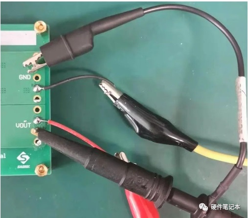
Figure 1 Error example
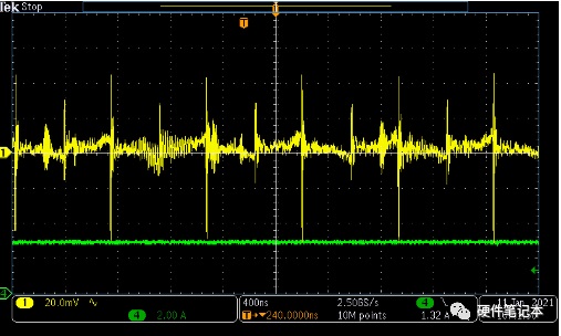
Figure 2 (CH1 output ripple CH4 output current)
The error of this test method is that it directly uses the long ground lead of the oscilloscope probe. This creates a large loop between the signal end and the lead, which can introduce additional inductance and cause severe ringing during the switching process. The large transient in the figure is not the actual output ripple of the switching regulator, but a measurement illusion.
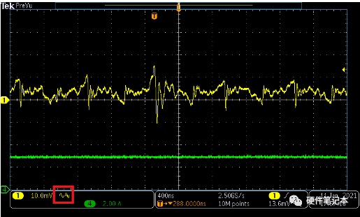
Figure 3 (CH1 output ripple CH4 output current)
Compared with Figure 2, Figure 3 is the result of the bandwidth limit of the oscilloscope under the same test method, which can only suppress the transient outside the bandwidth, and the measured state is still not the actual ripple state.
Improved test ripple
In order to reduce the stray inductance, the common method is to remove the long ground lead of the standard oscilloscope probe and connect its tube body to the ground reference point, so that the entire detection loop is minimized. We can do this by using an ECB to the probe tip adapter (Figure 4) or a coil. A common in-line resistor can be easily DIY into a coil (Figure 5).
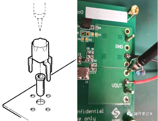
Figure 4 Using ECB to probe tip adapter Figure 5 Error example
Below is the output ripple shape measured using the above method. Compared with the waveform in Figure 3, the high-frequency transients have been significantly improved.
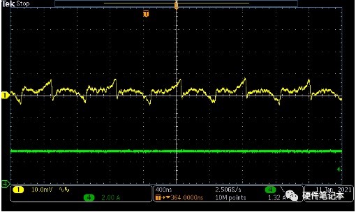
Figure 6 (CH1 output ripple CH4 output current)
But this is still not really the output ripple of a switching regulator. This is because the detection tip of the oscilloscope measures the output of the EVB board, and there is a parasitic inductance in the line between it and the output of the switching regulator.
In order to measure the true output ripple of the switching regulator, we propose to probe directly on the output capacitance instead, as shown in Figure 7.
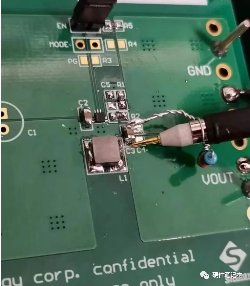
Figure 7 demonstrates proper operation
The following figure shows the output ripple shape measured using this method.
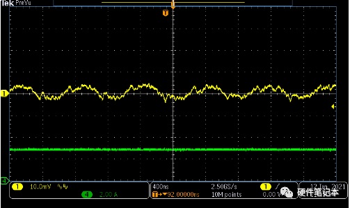
Figure 8(CH1 output ripple CH4 output current)
Correct operation demonstration
For applications that only need to care about the size of the output ripple peak, the results in Figure 8 are sufficient. However, if you want to know more details of the ripple, then the waveform in Figure 8 is not enough.
This is because we are using a common X10 oscilloscope probe, and the real signal will first go through 1/10 partial pressure into the oscilloscope for sampling. When the input ripple is small and after 1/10 partial voltage, it is close to the background noise of the oscilloscope, so the waveform in Figure 8 is actually superimposed with a lot of background noise of the oscilloscope.
Therefore, we recommend using a 1x passive probe or using a - coaxial cable, as shown in Figure 9.
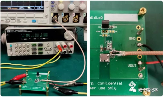
Figure 9 Recommended example
The output ripple shape of the switching regulator measured by coaxial cable is shown in Figure 11. In addition to more accurately measuring the peaking value of the output ripple, we can also see more details, such as ripple transients caused by the output capacitor ESL. These details can better assist engineers in the next step of the design.
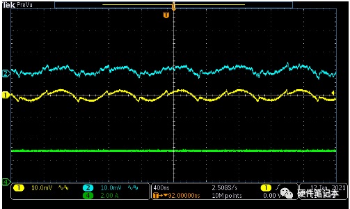
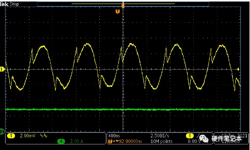
Figure 10 Test comparison of CH1 coaxial cable and CH2 10X probe
Figure 11 Output ripple of switching regulator measured using coaxial cable
Let‘s make a brief summary, the measurement method of the output ripple of the switching regulator can be summarized as follows:
1. Use oscilloscope bandwidth limit function;
2. Use ECB to probe tip adapter or coil for minimal loop ground;
3. Directly measure the signal at both ends of the voltage regulator output capacitor;
4. It is recommended to use a double probe or a coaxial cable for measurement.
|
Disclaimer: This article is transferred from other platforms and does not represent the views and positions of this site. If there is any infringement or objection, please contact us to delete it. thank you! |


 Business consulting

 13823761625
 Mail me