


Power amplifier output inductance selection and its influence on performance
Time:2024-05-03
Views:137
Previous articles have written about the influence of inductor selection on the frequency response and other indicators of the power amplifier, here the emphasis is on quantifying the inductor current under high power.
From the process point of view, first look at the starting current, inductive saturation current can carry? Then look at the horn current (the horn current depends on the acoustic engineer‘s pursuit of sound peak current) + inductive ripple current. The "horn current + inductor ripple current" is less than the saturation current of the inductor and has a margin of at least 25%, which is a relatively stable and reliable inductor selection scheme.
Inductive current measurement method:


The current flowing through the inductor is measured with the oscilloscope current probe in front of the filter capacitor
The current flowing through the inductor is equivalent to the current flowing through the chip MOS
During the test process, the inductor needs to be tilted up, and the other end of the inductor is welded to the pad with a thick wire, and the current probe clips the wire.
Power-on start current waveform:
Class D power amplifier is modulated by PWM (audio signal modulated at a higher PWM frequency). Taking conventional PWM modulation as an example, the unilateral output common-mode voltage is PVDD/2 (that is, the output duty cycle is 50%).
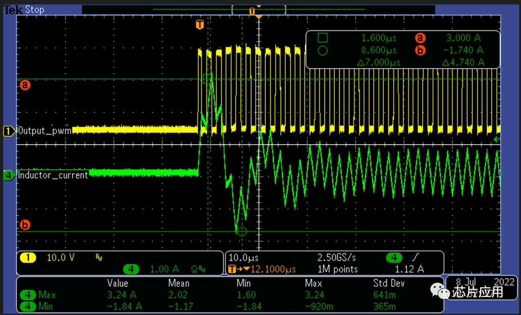
The green waveform is the inductive current flowing through, and the yellow waveform is the audio power amplifier output PWM.
The power supply voltage of the power amplifier PVDD=24V, the output LC (inductance is 10uH, capacitance is 0.68uF) The common-mode voltage is established immediately, and the oscillation current is about 3.2A.
Peak power-on start current Ipstart =PVDD * Duty *((C/L) ^0.5)*SIN(0.5*pi) (where Duty is PWM output Duty without input signal)

In SUMMARY:
1) For inductor selection, the first turn is to avoid the power-on current is too large to cause failure to start (power-on triggers overcurrent protection).
2) In many cases, the output speaker line current may be very small, less than 2A, but because the inductance value is selected too small, the establishment process of the starting common-mode voltage will exceed 2.5A.
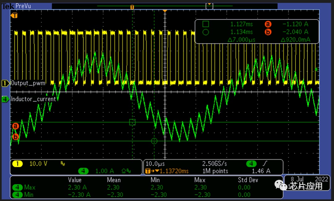
Output ripple current:
Class D power amplifier is modulated by PWM (audio signal modulated at a higher PWM frequency). Taking conventional PWM modulation as an example, when the output common-mode is stabilized, the inductance ripple is basically stable.

The green waveform is the inductive current flowing through, and the yellow waveform is the audio power amplifier output PWM;
Power amplifier supply voltage PVDD=24V, output LC (inductance is 10uH, capacitance is 0.68uF), switching frequency is 480kHz.
The higher the switching frequency, the smaller the ripple current; The larger the inductance, the smaller the ripple current. In general, in order to reduce the switching loss of the audio amplifier itself, the recommended switching frequency is 480kHz, so it is generally recommended that the inductance should not be less than 10uH when the inductance is greater than 12V.

In SUMMARY:
1) For inductance selection, after carrying the first start current, the next thing to consider is the maximum current flowing through the horn line superimposed ripple current.
Horn current superimposed inductive ripple current
The figure above is an example of inductance ripple current superimposed on horn current.
Take a horn with a DC resistance of R as an example (this does not consider the impedance of the horn at different frequencies is not the same, assuming that all frequencies are 4ohm; In addition, do not consider the RdsON of the power amplifier and the DCR of the inductor and wire), if the power is not limited on the power amplifier side, the maximum horn current is PVDD/R.
PVDD=19V, Load=4ohm, LC filter=10uH+0.68uF, switching frequency is 480kHz, modulation Mode is High Performance Mode, then the maximum current flowing through the inductor may be 5.29A.
Through this article, summarize the inductance current of the power amplifier, when the engineer chooses the inductance, the inductance current must be taken as a key indicator, the inductance current not only affects the index, but also affects the stability and life of the power amplifier.
In addition, in terms of materials, integrated molding and magnetic sealant also have an impact on the performance of the power amplifier, ACM8625 as an example, under the same configuration, just replace the saturation current is similar, and the inductance of different materials is compared with THD+N:

The yellow is one piece, and the blue is the magnetic sealant.
Inductance is an important part of the power amplifier system, I hope this article can help you, if it helps you, thank you for forwarding to your friend, I hope it can help him.
|
Disclaimer: This article is transferred from other platforms and does not represent the views and positions of this site. If there is any infringement or objection, please contact us to delete it. thank you! |


 Business consulting

 13823761625
 Mail me