


Brushless DC motor square wave, sine wave, FOC control
Time:2024-05-02
Views:136
I. Introduction
The brushless DC motor is developed on the basis of the brushed DC motor, with the advantages of endless speed regulation, wide speed regulation scale, strong overload capacity, good linearity, long life, small size, light weight, large output, etc., to deal with a series of problems existing in the brushed motor, widely used in industrial equipment, instrumentation, household appliances, robots, medical equipment and other fields. Because the brushless motor does not have a brush for active commutation, it needs to use an electronic commutator for commutation. The brushless DC motor driver performs the function of this electronic commutator.
Second, the mainstream brushless DC motor control method
At present, there are three main types: FOC (also known as vector control, magnetic field oriented control), square wave control (also known as trapezoidal wave control, 120° control, six-step commutation control) and voltage sine wave control. So what are the advantages and disadvantages of each of these three control methods?
1. Square wave control
Square wave control uses Hall sensor or non-inductive estimation algorithm to obtain the position of the motor rotor, and then reverses 6 times (once every 60°) according to the position of the rotor in a 360° electrical cycle. Each reversing azimuth motor outputs a force in a specific direction, so it can be said that the position accuracy of the square wave control is electrical 60°. Because under the control of this method, the phase current waveform of the motor is close to the square wave, it is called square wave control.
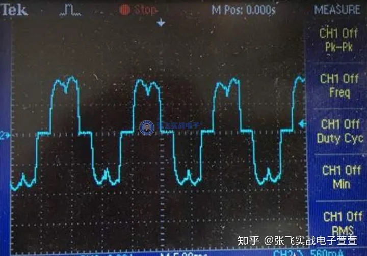
The advantages of square wave control method are simple control algorithm, low hardware cost, and higher motor speed can be obtained by using ordinary controller. The defect is that the torque ripple is large, there is a certain current noise, and the power cannot reach the maximum. Square wave control is suitable for occasions where the rolling function of the motor is not required. Figure 1 below shows the current waveform controlled by square wave:
2. General sine wave control
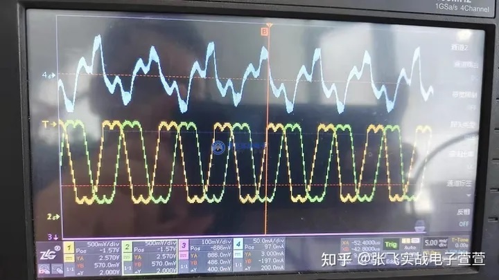
The general sine wave control method uses SVPWM wave, and the output is a 3-phase sine wave voltage, and the corresponding current is also a sine wave current in theory, but because the current is not controlled, the current waveform is not necessarily a real sine wave. This method has no concept of square wave controlled commutation, and may think that an infinite number of commutations are carried out in an electrical cycle. Obviously, the general sine wave control is compared with square wave control, the torque ripple is smaller, the current harmonics are less, and the control feels more "delicate", but the functional requirements of the controller are slightly higher than the square wave control, and the motor power can not be played to the maximum. Figure 2 below shows the current waveform and modulated wave (saddle wave) corresponding to the general sine control.
3. FOC control
Sine-wave control completes the control of voltage vector, but cannot control the direction of current. The FOC control method can be regarded as an upgraded version of sine wave control, which completes the current vector control, that is, the vector control of the stator magnetic field of the motor.
Because the direction of the motor stator magnetic field is controlled, the time between the motor stator magnetic field and the rotor magnetic field can be maintained at 90° to complete the maximum torque output of a certain current. The advantages of FOC control method are: low torque ripple, high power, low noise and fast dynamic response; The defects are: high hardware cost, high requirements for controller function, and motor parameters need to be matched. Figure 3 below shows the phase current waveform of the motor under FOC control.
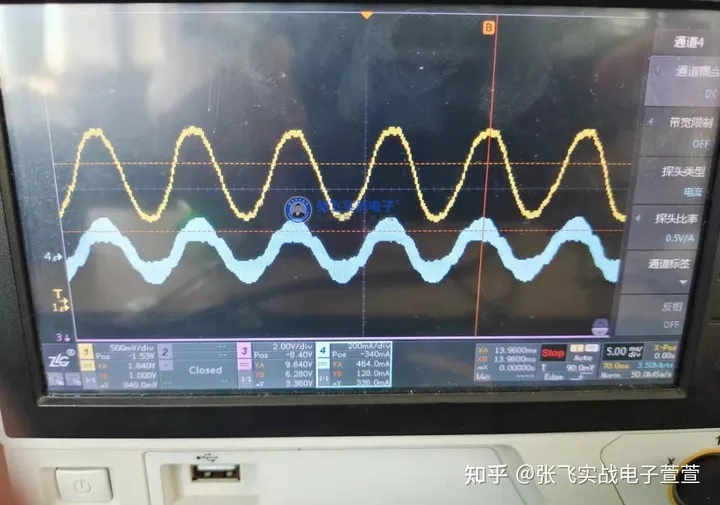
Figure 3: Motor phase current waveform during FOC control
FOC is now the best choice for efficient control of brushless direct current motors (BLDC) and permanent magnet synchronous motors (PMSM). FOC precisely controls the direction of the magnetic field, making the motor torque smooth, low noise, high power, and has a high-speed dynamic response. Because of the significant advantages of FOC, it has now gradually replaced traditional control methods in many uses, and has attracted much attention in the motion control profession, such as the field of servo control.
Typical control block diagram of FOC is shown in Figure 4 below. In order to obtain the motor rotor position, motor speed, current and other information as a reaction, the first need to collect the motor phase current, after a series of mathematical transformation and budget algorithm to get the decoupled easy-to-control reaction quantity. Then, according to the error between the reaction quantity and the target value, the dynamic adjustment is made, and the final output of 3-phase sine wave drives the motor to rotate.
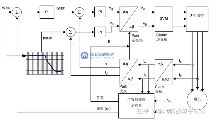
Figure 4: Sensorless FOC vector control block diagram
FOC can be divided into sensor FOC and sensorless FOC according to whether the motor has a sensor or not.
With regard to sensor FOC, because the sensor of the motor (generally Hall sensors or encoders, etc.) can reflect the position information of the motor rotor, the position estimation algorithm can not be used in the control, and the control is relatively simple, but the use of the motor with sensors often has higher requirements for the control function.
As for sensorless FOC, because the motor is not equipped with any sensor, the position information of the motor rotor cannot be obtained by simply reading the measured value of the sensor. Therefore, the rotor position is obtained by collecting the motor phase current and applying the position estimation algorithm in the control process. Although the control of non-inductive FOC is more difficult, it can prevent the danger of sensor damage, and save the cost of the sensor, and simplify the wiring between the motor and the drive board. At present, the non-inductive FOC is more used in the occasions of fans and pumps.
|
Disclaimer: This article is transferred from other platforms and does not represent the views and positions of this site. If there is any infringement or objection, please contact us to delete it. thank you! |


 Business consulting

 13823761625
 Mail me