


Application of Buck and Buck-Boost in auxiliary power supply of small household appliances
Time:2024-05-01
Views:137
In the ACDC power supply, the input voltage is generally from the power grid 85V-265V AC high voltage, and the output voltage is 3.3V, 5V, 12V and other DC low voltage, so the switching power supply is needed to achieve voltage reduction. The switching power supply has three classical topologies: Buck, Boost and buck-boost, in which Buck and buck-boost can realize the function of Buck reduction. Synergy Shihui is a subsidiary of Shihealth, with rich industry experience and professional technical strength, Shihui company power and new energy division FAE combined with their own experience, for small household appliances auxiliary power applications how to choose topological circuits and related products, launched a detailed introduction.
1. Buck circuit
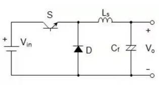
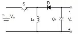
The Buck circuit is a buck circuit, Vi=Vls+Vo. Because Vi>Vo, it has antihypertensive effect.
(1) Switching tube S conduction stage
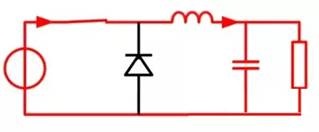
When the switch is closed, the continuous current diode D is cut off, and since the input voltage Vi is connected to the energy storage inductor Ls, the input-output pressure difference (VI-VO) is added to the Ls, so that the current through the Ls increases linearly. At this stage, in addition to supplying power to the load, a portion of the electrical energy is stored in the inductor Ls and the capacitor Cr.
(2) Switching tube S off stage
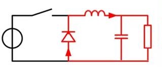


When the switch is disconnected, Ls is disconnected from Vi, but since the inductor current cannot change instantaneously, a reverse electromotive force is generated on the inductor Ls to maintain the current through. At this time, the continuous current diode D is switched on, and the electrical energy stored in the inductor Ls is supplied to the load through a loop composed of D. (Mainly capacitor C supplies power to the load, and always charges the capacitor at this stage to maintain voltage stability)
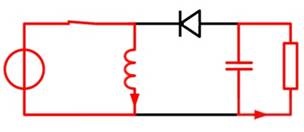
2.Second, Buck-Boost circuit
The input voltage of a Buck-Boost circuit has the opposite polarity to the output voltage.
(1) Switching tube S conduction stage
When the switch is closed, the input voltage is returned directly through the inductor L, stored on the inductor Ls, and the capacitor Cr is discharged to supply power to the load.
(2) Switch tube S cut-off stage
When the switch is turned off, a reverse electromotive force is generated on the inductor Ls, causing diode D to change from cutoff to on-conduction. The inductor supplies power to the load and charges the output capacitor, keeping the output voltage constant.
From the above comparison, it can be seen that the polarity of the input voltage and the output voltage of Buck-Boost circuit is opposite. Therefore, the biggest difference between Buck and buck-Boost lies in the polarity of the input voltage and the output voltage: Buck is a homopolar topology, that is, the polarity of the output voltage and the input voltage are the same. Buck-Boost is a reverse polarity topology, in which the output has the opposite polarity to the input voltage, and the output provides negative pressure (relative to the input voltage).
In the power module control part of small household appliance application scenarios, engineers commonly use AC switches such as bidirectional thyristors (TRIAC). By using negative pressure to drive AC switches, higher circuit reliability and compatibility can be achieved. Buck-Boost, which can output negative pressure, is often preferred in systems using AC switches. In systems that do not require a negative pressure drive, the Buck topology can be selected:
• The input and output terminals of Buck are common, which is more conducive to multi-level expansion of the system.
• The inductive current utilization of Buck is higher than buck-boost. When the inductive current (IL) is the same, Buck can output a larger current (IO).
|
Disclaimer: This article is transferred from other platforms and does not represent the views and positions of this site. If there is any infringement or objection, please contact us to delete it. thank you! |


 Business consulting

 13823761625
 Mail me