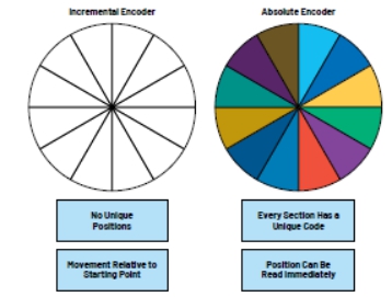
Figure 3. Encoder Type
Table 1. Key Performance Indicators of Encoder
|
index
|
define
|
notes
|
|
resolution ratio
|
Number of distinguishable positions per encoder revolution (n)
|
High resolution: 16 bits to 24 bits
Medium resolution: 13 bits to 18 bits
Low resolution:<12 bits
|
|
Absolute accuracy
|
The difference between the actual position and the reported position after one revolution (similar to INL)
|
Position control applications rely on absolute accuracy
|
|
Differential accuracy
|
The difference between the reported distance and the ideal distance between two adjacent positions (similar to DNL)
|
Speed control applications rely on differential accuracy
|
|
repeatability
|
Consistency of encoder returning to the same instruction position
|
Repeatability is important for repetitive tasks, such as those involving robots
|
The importance of motor encoder accuracy and repeatability
SMT machines/robots are commonly used automated machines in the food packaging and semiconductor manufacturing industries. In order to improve process efficiency, machines or robots with high precision and repeatability are needed. The use of high-performance motor encoders can achieve high accuracy, repeatability, and efficiency.
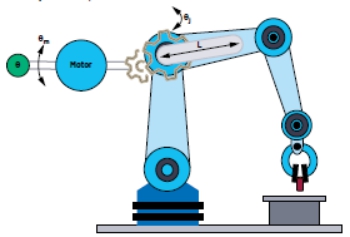
Figure 4 shows the application case of encoders in robots. The motor drives each joint in the machine arm through a precision reduction gearbox. The robot joint angle is achieved through a precision shaft angle encoder installed on the motor( θ m) And additional encoders installed on the machine arm( θ j) To measure.
For robots, the main performance specification listed in the data manual is repeatability, which is usually on the order of submillimeter. After understanding the repeatability specifications and the scope of action of the robot, the specifications of the rotary encoder can be inferred.
Figure 4. Motor encoder( θ m) And joint encoder( θ j) Repeatability of angles and robot range of action (L)
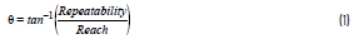
Angle repeatability required for joint encoder( θ) It can be concluded from the Trigonometric functions that the repeatability of the robot is divided by the arctangent of the scope of action.
The combination of multiple joints can achieve the overall range of action of the robot. Sensors should have higher performance than target angle accuracy. It is necessary to improve the repeatability specifications of each joint, assuming an improvement of 10 times. For motor encoders, repeatability is defined by gear ratio (G).
For example, for the robot system shown in Table 2, the joint encoder requires a repeatability specification of 20 to 22 bits, while the motor encoder requires a resolution of 14 to 16 bits.
Table 2. Encoder Repeatability and Robot Repeatability Specifications
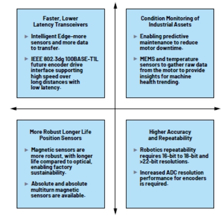
Figure 5 illustrates the future development trends of encoders and the technologies to implement these trends.
Figure 5. Encoder Development Trends and Technologies to Implement These Trends
Rockwell 1‘s research on servo drivers, encoders, and encoder communication ports shows that the number of transceivers used for feedback communication increases by 20% annually. A single pair Ethernet (SPE) transceiver that supports 100 Mbps communication over two lines (IEEE 802.3dg standard 100BASE-T1L) is currently being studied, and future encoder driver interfaces will benefit from low latency with a target performance of ≤ 1.5 µ s. This low latency will support faster feedback data collection and shorter control loop response time.
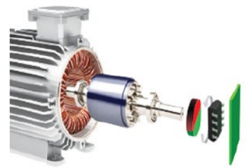
The monitoring of the status of robots and rotating machines (such as turbines, fans, pumps, and motors) records real-time data related to the health and performance of the machines for targeted predictive maintenance and optimization control. Targeted predictive maintenance in the early stages of the machine lifecycle can reduce the risk of production downtime, thereby improving reliability, significantly saving costs, and improving factory productivity. Placing MEMS accelerometers in encoders can provide Haptic technology of the machine, which is suitable for applications where quality control is critical. It is convenient to add MEMS accelerometer to the encoder, because the encoder has off the shelf wiring, communication and power supply, which can provide Haptic technology to the controller. In some applications such as CNC machine tools, MEMS vibration data sent from encoders to servers can be used to optimize system performance in real-time.
The use of CbM combined with robust and longer lifespan position sensors can extend the service life of industrial assets. Magnetic sensors generate analog outputs indicating the angular position of the surrounding magnetic field, which can replace optical encoders. Magnetic encoders can be used in areas with high humidity, severe dirt, and dust. These harsh environments can affect the performance and lifespan of optical solutions.
For robots and other applications, the position of the mechanical system must always be clear, even in the event of a power outage. Standard robots, collaborative robots, and other automated assembly equipment require resetting and initializing the power supply after a sudden power outage during operation, which incurs certain related costs and leads to low efficiency. The magnetic multi turn memory 2 developed by ADI company can record the number of rotations of the external magnetic field without the need for an external power source, thus reducing system size and cost.
For robots and collaborative robots, motor encoders and joint encoders typically require 16 to 18 bit ADC performance, and in some cases, 22 bit ADC is required. Some optical absolute position encoders also require high-performance ADC with a resolution of up to 24 bits.
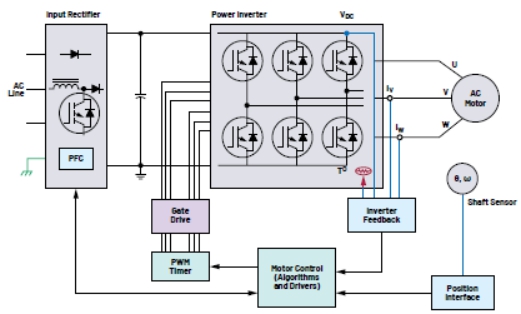
Motor encoder signal chain
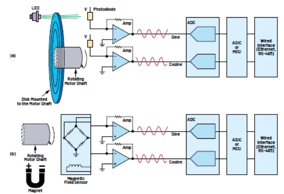
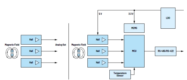
Figures 6, 7, 8, and 9 show the encoder signal chains of magnetic (anisotropic magnetoresistance (AMR) and Hall technique), optical, and rotary encoders. The main components are divided into five categories:
1. Use magnetic sensors (AMR, Hall) to track axis position and speed
2. Equipment health monitoring
a. MEMS sensors
b. Temperature sensor
3. Intelligence
a. Microcontroller with/without integrated ADC
b. Rotary digital converter (RDC)
4. Cable interface
a. High speed RS-485/RS-422 transceiver
b. SPI to RS-485 extender transceiver
5. Signal conditioning
a. High performance ADC (12 bit to 24 bit resolution)
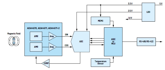
Magnetic encoder (AMR) detection
In the field of magnetic position sensor applications, AMR sensors have both stable and reliable performance and high accuracy. As shown in Figure 6, the sensor is usually located opposite the dipole magnet installed on the motor shaft.
Figure 6. AMR sensor system
AMR sensors are sensitive to changes in magnetic field direction, while Hall technology is sensitive to magnetic field intensity. So sensors have a strong tolerance for air gaps and mechanical tolerance changes in the system, which is very advantageous. In addition, the working magnetic field of AMR sensors has no upper limit, so this type of sensor is almost unaffected by stray magnetic fields when operating under high magnetic fields.
ADA4571 is an AMR sensor with low delay integrated signal conditioning function, providing single ended analog output. The ADA4571 single-chip solution provides good angular accuracy (typical angular error is only 0.10 degrees), and can operate at speeds up to 50k rpm. ADA4571-2 is a dual channel version that provides complete redundancy without affecting performance, making it suitable for safety critical applications.
ADA4570 is a derivative product of AAD4571, which has the same performance but provides differential output, suitable for more harsh environments. The high angle accuracy and repeatability provided by the ADA457x series improve closed-loop control, reducing motor torque ripple and noise. Compared to competitive technologies, single chip architecture improves reliability, reduces size and weight, and is easier to integrate.
Signal conditioning and power supply
AD7380 4 MSPS dual channel synchronous sampling, 16 bit SAR ADC has many system level advantages, including space saving of 3mm × A 3mm package is crucial for encoder PCB boards with limited space. 4 MSPS throughput rate ensures the capture of detailed information on sine and cosine cycles, as well as the latest encoder position information. The high throughput rate supports the implementation of on-chip Oversampling, thus reducing the time delay when digital ASICs or microcontrollers feed back accurate encoder positions to motors. Another advantage of the AD7380 on-chip Oversampling is that it can add an additional 2-bit resolution, which can be easily used with the on-chip resolution enhancement function. The Oversampling and resolution enhancement functions of AD7380 are introduced in detail by using note AN-20033. The VCC and VDRIVE of the ADC, as well as the power rail of the amplifier driver, can be powered by an LDO regulator (such as LT3023). Multiple low noise LDO outputs such as ADP320, LT3023, and LT3029 can be used to power all components in the signal chain.
transceiver
The ADM3066E RS-485 transceiver has ultra-low transmitter and receiver bias performance, making it very suitable for transmitting precision clocks. Motor control standards such as EnDat 2.24 typically require precision clocks. It has been proven that the deterministic jitter of ADM3065E using typical cable lengths in motor control applications is less than 5%. The ADM3065E has a wide power supply voltage range, so this timing performance level can also be used for applications that require a 3.3 V or 5 V transceiver power supply. For more information, please refer to the technical article "Using fieldbus to improve speed and expand coverage" 5.
Microcontroller
For applications that require 12 bit or lower resolution, an integrated ADC microcontroller can be used instead of the AD7380 ADC. Compact MAX32672 Ultra Low Power Arm ® Cortex ®- The M4F microcontroller includes a 12 bit 1 MSPS ADC with enhanced security, peripherals, and power management interfaces.
Figure 7. Magnetic Encoder (AMR) Signal Chain
Asset condition monitoring
ADXL371 is an ultra low power, 3-axis, digital output, ± 200g Micro Electro Mechanical System (MEMS) accelerometer suitable for machine monitoring. ADXL371 has high cost-effectiveness and is designed with a small size of 3mm × 3 mm package, operating temperature up to+105 ° C. In instant conduction mode, ADXL371 consumes 1.7 μ A‘s current, while continuously monitoring environmental impacts. When an impact event is detected that exceeds the internally set threshold, the device switches to normal operating mode, which is very fast for recording events.
ADT7320 is a high-precision digital temperature sensor that does not require user calibration or calibration, and has excellent long-term stability and reliability. The rated operating temperature range of ADT7320 is -40 ° C to+150 ° C, using a small size of 4 mm × 4mm LFCSP package.
Table 3. Recommended Components for Magnetic Encoder (AMR) Signal Chain
|
element
|
Recommended product model
|
|
mems accelerometer
|
ADXL371、ADXL372、ADXL314、ADXL375
|
|
temperature sensor
|
ADT7320
|
|
Power supply (LDO regulator)
|
ADP320、LT3023、LT3029
|
|
ADC, 12 bit, 16 bit SAR
|
MAX11198、AD7380、AD7866
|
|
AMR magnetic sensor
|
ADA4570、ADA4571、AD4571-2
|
|
Dual channel comparator
|
LTC6702
|
|
Transceivers (RS-485, RS-422)
|
MAX22506E、ADM3066E、ADM4168E、MAX22500E
|
|
Microcontroller, integrated ADC
|
MAX32672、MAX32662
|
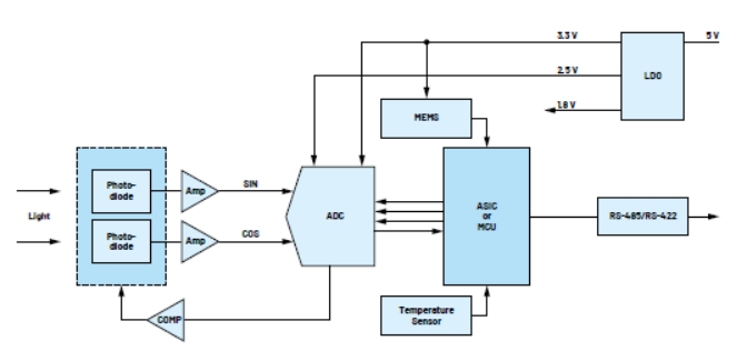
Optical encoder
The optical encoder signal chain components are almost identical to the components introduced in the magnetic encoder (AMR) section. However, in order to support higher encoder resolution, it is recommended to use AD7760 2.5 MSPS, 24 bit, 100 dB Σ-Δ ADC. It combines wide input bandwidth, high-speed characteristics, and Σ-Δ The advantage of conversion technology is that the signal-to-noise ratio (SNR) can reach 100 dB at 2.5 MSPS, making it very suitable for high-speed data acquisition applications.
Figure 8. Magnetic encoder (Hall) signal chain
Figure 9. Optical encoder signal chain
Table 5. Recommended Components for Optical Encoder Signal Chain
|
element
|
Recommended product model
|
|
mems accelerometer
|
ADXL371、ADXL372、ADXL314、ADXL375
|
|
temperature sensor
|
ADT7320
|
|
Power supply (LDO regulator)
|
ADP320、LT3023、LT3029
|
|
ADC, 12 bit, 16 bit, 24 bit
|
MAX11198、AD7380、AD7866、AD7760
|
|
Precision operational amplifier
|
ADA4622-4
|
|
Dual channel comparator
|
LTC6702
|
|
Transceivers (RS-485, RS-422)
|
MAX22506E、ADM3066E、ADM4168E、MAX22500E
|
|
Microcontroller, integrated ADC
|
MAX32672、MAX32662
|
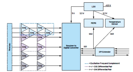
Rotary transformer (coupling) encoder
The rotary encoder has some advantages, such as high mechanical reliability and high accuracy; However, compared to magnets and ADA4571, the price of the rotary transformer is expensive.
AD2S1200 will convert the signal of the spin converter into digital angle or angular rate. Figure 10 shows the signal chain of the rotary transformer. Two amplifiers are used to create a third-order Butterworth low-pass filter to transmit the converter signal to AD2S1200. For more information, please refer to circuit note CN0276.
To save space and reduce design complexity, it is recommended to use the LTC4332 SPI extender. LTC4332 supports system partitioning and provides the option to place the microcontroller in the server instead of the encoder. If the encoder requires a microcontroller, it can be directly connected to AD2S1200 using the MAX32672 SPI interface, and an ADM3065E RS-485 transceiver can be used instead of LTC4332.
If LTC4332 is used, the AD2S1200 SPI output will be converted to a robust differential fieldbus interface. LTC4332 includes three slave selection lines, so external sensors such as MEMS and temperature sensors can be connected to the same bus as AD2S1200.
Table 6. Recommended components for rotary encoder signal chain
|
element
|
Recommended product model
|
|
mems accelerometer
|
ADXL371、ADXL372、ADXL314、ADXL375
|
|
temperature sensor
|
ADT7320
|
|
Power supply (LDO regulator)
|
ADP320、LT3023、LT3029
|
|
Precision operational amplifier
|
ADP320、LT3023、LT3029
|
|
Transceivers (RS-485, RS-422)
|
LTC4332、ADM3065E
|
|
Rotary digital converter
|
AD2S1200、AD2S1205、AD2S1210
|
conclusion
ADI Corporation utilizes its profound domain expertise and advanced technology to assist partners in designing future industrial motor encoders and networks. By utilizing a compact and powerful microcontroller, ADXL371 MEMS accelerometer, and ADT7320 temperature sensor, asset health insight can be easily integrated into the encoder. Compared to optical or rotary transformer detection solutions, ADI‘s advanced AMR magnetic sensors (such as ADA4571) improve reliability, reduce size and weight, and are easier to integrate into encoders. Adopting mid to high end ADCs such as AD7380 or AD7760 can achieve the high precision and repeatability required for SMT machines and robots.
Figure 10. Rotary encoder signal chain
References
1. Dayin Xu. 100BASE-T1L for motor feedback communication. "Rockwell Automation, May 2022.
2. Stephen Bradshaw, Christian Nau, and Enda Nicholl. Multi turn position sensor (TPO) with true power on capability and zero power consumption. "Analog Dialogue, Vol. 56, Issue 3, September 2022.
3. Jonathan Colao. "On film Oversampling of ADI‘s AD7380 series SAR ADC." ADI, June 2020.
4. "EnDat 2.2- Bidirectional interface for position encoders." Heidenhain, September 2017.
5. Richard Anslow and Neil Quinn. Utilizing fieldbus to increase speed and expand coverage. "ADI Company, March 2020.
About ADI Company
Analog Devices, Inc. (NASDAQ: ADI) is a leading semiconductor company globally committed to bridging the gap between the real world and the digital world to achieve breakthrough innovation in the field of intelligent edges. ADI provides solutions that combine analog, digital, and software technologies to promote sustainable development in fields such as digital factories, automobiles, and digital healthcare, address climate change challenges, and establish reliable connectivity between humans and everything in the world. ADI Company‘s revenue in the fiscal year 2022 exceeded $12 billion, with over 24000 employees worldwide. Joining hands with 125000 customers worldwide, ADI helps innovators constantly surpass all possibilities. For more information, please visit www.analog.com.
About the author
Richard Anslow is a senior manager in the Industrial Automation Division of ADI Company, engaged in software system design engineering. His areas of expertise are state monitoring, motor control, and industrial communication design. He holds a Bachelor of Engineering degree and a Master of Engineering degree from the University of Limerick, Ireland. Recently, he completed the postgraduate courses of Artificial Intelligence (AI) and Machine Learning (ML) at Purdue University.
|
Disclaimer: This article is transferred from other platforms and does not represent the views and positions of this site. If there is any infringement or objection, please contact us to delete it. thank you!
矽源特科技ChipSourceTek
|


 Business consulting

 13823761625
 Mail me