


How to reduce the size of the voltage regulator
Time:2023-07-24
Views:807
If only reducing the size of the voltage regulator was as simple as this. But in most cases, the available circuit board space is always insufficient to accommodate all components, and the limited space needs to carry more features and functions. High integration and Moore‘s law are very effective in reducing the size of equipment, but they have little effect on DC/DC converters, because power converters often occupy 30% to 50% of the system space. So, how can we break through this bottleneck?
Increasing work frequency is undoubtedly an obvious solution. Most load point regulators are switch converters with buck topology. Increasing the switching frequency can reduce the inductance and capacitance required to meet the Design specification of the voltage regulator. Given that inductors and capacitors typically occupy most of the DC/DC converter space, as shown in Figure 1 (a), this approach may be very effective. But in fact, it‘s not that simple. So, why on earth?
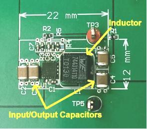
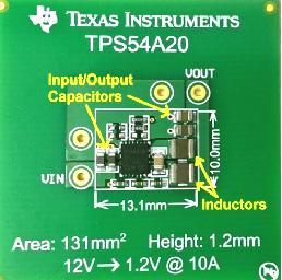
Figure 1: Comparison of the dimensions of the 12VIN, 10AOUT buck converter (a) and the series capacitor (b) at 2MHz per phase at 500kHz
Blindly increasing frequency will increase power consumption. The switching frequency is proportional to the loss, and energy consumption is generated every time the power supply is switched on or off. Among them, the decrease in conversion efficiency and heat dissipation may be the main issues. Nowadays, the frequency of most converters is limited to the range of hundreds of kilohertz. Converters with frequencies above 1MHz are typically of low voltage (5V and below) and low current (less than 1A) types.
It‘s time to look for other solutions beyond the scope of reducing blood pressure. For decades, buck converters have been the industry‘s primary solution, but at the same time, they also have fundamental flaws. Now, we have launched a new DC/DC converter topology that has been optimized for applications with high voltage conversion ratio load points. The series capacitor step-down converter can achieve operating frequencies of several megahertz without affecting efficiency. As shown in Figure 1 (b), the overall solution size has been significantly reduced. The series capacitor step-down converter based on TPS54A20 has the same input and output conditions as the step-down converter in Figure 1 (a), but its size is 8 times smaller than the latter. Namely 1270 mm3 vs. 157 mm3.
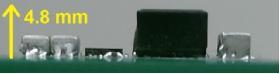
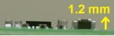
Figure 2: Height comparison of 12 VIN, 10 AOUT Buck converter (a) at 500kHz and series capacitor (b) at 2MHz per phase
The reduction in voltage regulator size provides us with more opportunities. By comparing the height profile shown in Figure 2, we can see that the height of the conventional Buck converter is 4.8mm, but for the back part, this height is far beyond the height limit of many systems. The low cross-section of the series capacitor step-down converter (1.2mm high) allows you to place the voltage regulator on the back of the circuit board, which can release valuable top side substrate surface. Previously, it was not practical to place the entire 10A converter on its back due to the large volume of passive components, but now with TPS54A20, everything is possible.
|
Disclaimer: This article is transferred from other platforms and does not represent the views and positions of this site. If there is any infringement or objection, please contact us to delete it. thank you! |


 Business consulting

 13823761625
 Mail me