


LLC Resonant converter designed for audio applications
Time:2023-07-21
Views:813
Author: Giovanni Maria

For designers, power conversion design in the audio field is a real technical challenge, as peak loads may be much higher than the root mean square (RMS) power requirements. They must strike an optimal balance between heat dissipation requirements, size and weight of the solution, cost, and of course, efficiency.
1. High power audio
Today, a fairly common choice for high power audio applications with peak loads is the LLC Resonant converter. This type of converter has many advantages, such as higher efficiency and reliability compared to other solutions. It is a power converter composed of three reactance components, which utilizes resonance between the coil and capacitor and achieves efficient power conversion through oscillation at a specific frequency (referred to as resonance frequency).
There are some important factors to consider when designing LLC Resonant converter for audio applications. Firstly, the resonant frequency of the circuit must be carefully selected based on the application specifications. Inductors and capacitors must be selected based on the power of the application and the required resonant frequency, and must have the highest quality. The coil must have a sufficiently high inductance to avoid core saturation effects during peak load current, while the capacitor must be able to handle the voltage and current of the circuit. Pay attention to the sound track in Figure 1, which highlights several elements of the track, including:
RMS audio level: RMS audio level represents the effective amplitude of the audio signal in the time domain. It is usually used to represent the true level of audio signals, as it considers both the positive and negative amplitudes of the signal. RMS audio level is usually expressed in decibels relative to the power reference. This level is important because it represents the actual power of the audio signal.
Peak audio level: The peak audio level represents the maximum amplitude value of the audio signal in the time domain. It is the maximum instantaneous audio power, representing the highest peak point reached by the signal within a given time period. The peak level is usually measured in decibels relative to the amplitude reference. Peak is an indicator of the maximum amplitude of a signal, which can be used to avoid distortion or clipping of audio signals. Measuring peak audio levels is crucial to ensure that the signal does not exceed acceptable amplitude limits and to avoid unnecessary distortion or damage to speakers or playback devices.
Peak factor: The peak factor in audio is a measure indicating the difference between the peak level and RMS level of the audio signal. Its calculation method is to divide the peak value of the audio signal by its RMS value. For example, if the peak value of the signal is 2V and its RMS value is 1V, then the peak factor is equal to 2. The peak factor is important because it provides information about the dynamics of audio signals. A high peak factor indicates a significant difference between the peak and RMS levels, indicating that the signal has greater dynamics and may contain high amplitude transients or peaks. On the contrary, low peak factor represents lower dynamics and more compressed or limited signals. High peak factor requires a different approach from low peak factor to manage signal dynamics and ensure that the signal itself remains within an acceptable range without unnecessary distortion or clipping.
Figure 1: Relationship between peak audio level and RMS audio level
The basic requirement for power supplies is that they must be able to instantly support peak loads several times the rated load. Although this situation may rarely occur, the power supply system must be prepared for this possibility. The following is a list of conventional measurements of peak factor for different types of sound:
·Environmental noise: 3:1
·Speech: 4:1
·Music with peak level compression: 4:1 to 8:1
·Music without peak level compression: 8:1 to 10:1
·Movie audio:>10:1
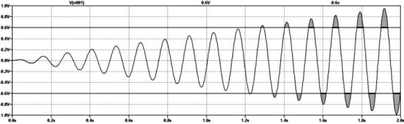
If the output voltage of the power supply excessively decreases during the peak load transient, clipping will occur (see waveform diagram in Figure 2), and due to many audio information being cut, the audio will be completely distorted. In addition, the adverse effects not only involve sound, but also the electronic parts of the system, especially:
·Due to the mechanical limitations of subwoofers (subwoofers), they face significant risks. If the vibration of the speaker exceeds expectations, both the sound cone and coil may be damaged.
·The subwoofer or tweeter itself may overheat due to the high energy passing through the audio cable.
·The sound reproduction is highly distorted because the audio signals of the upper and lower peaks are cut.
Having a powerful power supply is a basic requirement for the circuit, and its output voltage must be maintained within a precise overshoot and undershoot limit. In the past, although the efficiency of electronic tube systems was very low (essentially generating a large amount of unused heat), audio signal distortion was rarely observed, either due to high voltage or power supply.
Figure 2: Insufficient power supply may cause clipping.
Some commonly used solutions for optimal audio power supply include using a larger proportion of PCB footprint or reducing circuit size by using higher switching frequencies and smaller magnetic components.
2. Let‘s take a look at LLC specifically
As mentioned earlier, implementing LLC solutions in the audio field requires comprehensive collaboration and communication between power and audio engineers. Before designing the power supply, it is necessary to specify the continuous power and peak power that the audio amplifier can handle. The ratio of peak power to continuous power (as shown in the table above) depends on the specific application, so it needs to be clearly defined at the beginning of the design.
LLC series Resonant converter (LLC-SRC) is a specific configuration of LLC Resonant converter, which is used as an isolated DC/DC converter. In the LLC-SRC configuration, the LLC converter (see Figure 3) is connected in series with a transformer and a rectifier diode to achieve Galvanic isolation between the input and output of the converter. Transformers can increase or decrease input voltage according to the needs of the application.
This configuration has several advantages. Firstly, it provides high efficiency by utilizing resonance between the coil and capacitor, thereby reducing switching losses. In addition, the Galvanic isolation provided by the transformer allows the input and output of the converter to be separated, thus protecting the control circuit and allowing adjustment of the transformer ratio. From the gain response curve, it can be seen that there are three different situations depending on the switching frequency.
If the switching frequency is less than the resonant frequency:
·Secondary DCM operation
·Soft switching rectifier (ZCS)
·Higher RMS current at given power
If the switching frequency is equal to the resonant frequency:
·Restrict secondary DCM/CCM operations
·Soft switching rectifier (ZCS)
·Best efficiency point
If the switching frequency is greater than the resonant frequency:
·Secondary CCM operation
·Reverse recovery of rectifiers
·Low RMS current at given power
Therefore, the ideal goal is to operate close to the resonant frequency at rated load and below the resonant frequency during peak load. Once the design specifications are defined, the design of the power supply can continue. According to the power quality standards of the region and application, the power design may require a power supply with power factor correction function. The first key design step is to select resonant circuit components to set the resonant frequency and determine the gain characteristics. At this stage, the output voltage must be sufficient to operate the system at peak power levels. If the circuit cannot achieve the required gain, the output voltage will decrease during the peak power period, thereby reducing audio quality or causing amplifier failure. The duration of peak power may be quite long, so the power supply must be able to continuously supply the entire peak load.
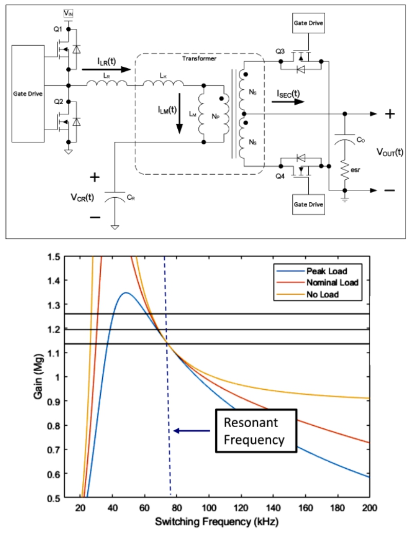
Figure 3: Schematic diagram of LLC resonant converter
The Key Stage of the operation happens during the peak power signal, so it is very important to use first-class components that can handle this current, and the magnet must not be saturated. On the other hand, during continuous power supply, components must ensure their rated thermal performance. Designing a PCB that is suitable for heat dissipation is usually more convenient than designing a heat sink. LLC-SRC is usually designed in burst mode to ensure efficiency under light loads and meet industry standards for standby power. This can reduce standby power consumption without turning off the main output.
conclusion
The design of Resonant converter is very challenging, especially when they are used with audio systems. They are effective solutions for high-power music applications with peak load. The design of LLC Resonant converter needs to select resonant frequency wisely, select coil and capacitor correctly according to application specifications, and design phase control to handle peak load. The correct design of the LLC Resonant converter ensures efficient and reliable operation of the application, even if it is very complex. The efficiency of the audio amplifier should always be considered, as its loss can lead to an increase in load on the power supply.
|
Disclaimer: This article is transferred from other platforms and does not represent the views and positions of this site. If there is any infringement or objection, please contact us to delete it. thank you! |


 Business consulting

 13823761625
 Mail me