


Main types and working principles of push-pull amplifier
Time:2022-08-30
Views:1832
When the demand for long-distance audio communication increases, it is necessary to increase the amplitude of electrical signals in order to transmit them over a long distance. Although a variety of ways were used to amplify the signal in the early stage, the effect was still unsatisfactory. About 1912, the world first introduced amplifiers, that is, devices that can amplify to increase the power of input signals.
In the early amplifiers, vacuum tubes were used and later replaced by transistors in the 1960s. Based on the active circuit and functional operation used to design them, there are many types of amplifiers, including the power amplifier that increases the available power of the load, and the push-pull amplifier is one of the power amplifiers.
What is a push-pull amplifier
A push-pull amplifier is a power amplifier used to provide high power to a load. It consists of two transistors, one is NPN and the other is PNP. One of the transistors pushes the output in the positive half cycle and the other pushes the output in the negative half cycle. In short, one transistor pushes the current in one direction, while the other transistor pulls the current in the other direction, which is why it is called a push-pull amplifier.
These amplifiers are more efficient than single ended class a amplifiers. Since the transistors in the push-pull amplifier are inverted, the difference between the outputs of the two transistors is provided to the load. Even harmonics present in the signal are eliminated. This method reduces distortion in the signal due to nonlinear components.
Main types
Push-pull amplifiers are mainly divided into three categories, but generally class B amplifiers are defaulted to be push-pull amplifiers.
Class a push-pull amplifier
Class B push-pull amplifier
Class AB push-pull amplifier
The following will introduce the three types of circuits in turn, and the required materials are as follows:
Transformer (6-0-6)
Bc557-pnp transistor
2n2222-npn transistor
Resistor – 1K (2 off)
LED
1. Class a push-pull amplifier
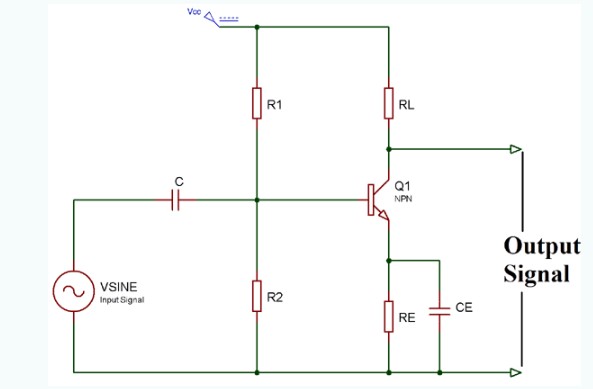
Class A is the most common power amplifier configuration, which consists of only one switching transistor set to always keep on, producing the minimum distortion and maximum amplitude of the output signal. The efficiency of class a push-pull amplifier is very low, close to 30%. Even if the input signal is not connected, the stage of the class a push-pull amplifier allows the same amount of load current to flow through it, so the output transistor needs a large heat sink. The circuit diagram of class a push-pull amplifier is as follows:
2. Class B push-pull amplifier
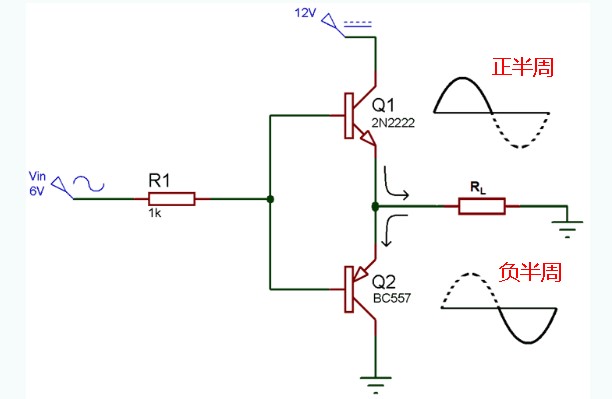
The class B push-pull amplifier is an actual push-pull amplifier. The efficiency of class B push-pull amplifier is higher than that of class A, reaching 78.9%, because it is composed of two transistors NPN and PNP. The class B push-pull amplifier circuit is biased in such a way that each transistor will operate over half a cycle of the input waveform. Therefore, the conduction angle of such an amplifier circuit is 180 degrees. One transistor pushes the output in the positive half cycle and the other pushes the output in the negative half cycle. The circuit diagram of class B push-pull amplifier is as follows:
In addition, class B is usually affected by what is called cross distortion, where the signal is distorted at 0V. It is well known that the base emitter junction of a transistor requires a voltage of 0.7V to open. Therefore, when the AC input voltage is applied to the push-pull amplifier, it increases from 0 until it reaches 0.7V, and the transistor remains in the off state without any output. The same thing happens to the PNP transistor in the negative half cycle of the AC wave, which is called the dead zone. To overcome this problem, the diode is used for bias, and then the amplifier is called class AB amplifier.
3. Class AB push-pull amplifier
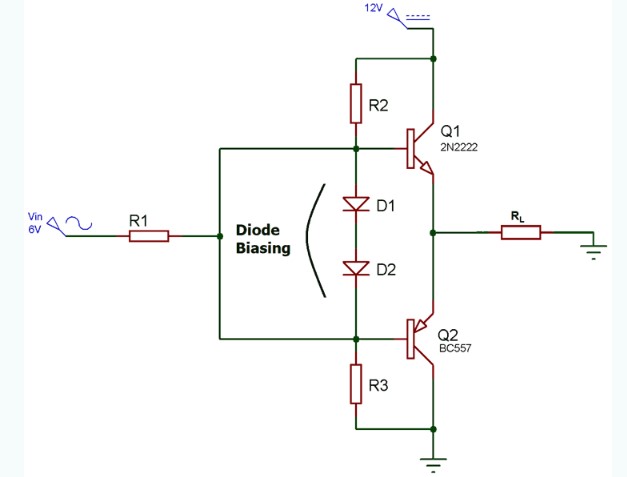
A common method of eliminating cross distortion in class B amplifiers is to bias two transistors at a point slightly above the transistor cutoff point. Then this circuit is called the class AB amplifier pull-up circuit, and its circuit diagram is as follows:
It can be seen that the class AB amplifier pull-up circuit is actually a combination of class A and class B amplifiers. By adding a diode, the transistor is biased to a slight on state even when there is no signal at the base terminal, thereby eliminating the cross distortion problem.
working principle
The schematic diagram of the push-pull amplifier circuit is composed of two transistors Q1 and Q2, respectively NPN and PNP. When the input signal is positive, Q1 begins to conduct and produces a copy of the positive input at the output. At this time, Q2 is still closed.
In this case, V out = V in – V be1.
Similarly, when the input signal is negative, Q1 is turned off, Q2 is turned on, and a copy of the negative input is generated at the output.
In this case, V out = V in + V be2.
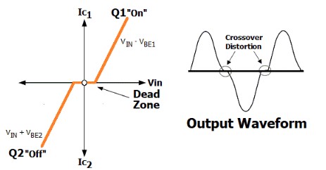
Now why does cross distortion occur when V in reaches zero? You can see the rough characteristic diagram and output waveform of the push-pull amplifier circuit shown below.
It can be seen that transistors Q1 and Q2 cannot be turned on at the same time. To turn on Q1, V in must be greater than V out, and for Q2, V in must be less than V out. If V in is equal to 0, Vout must also be equal to 0.
Now, when V in increases from zero, the output voltage Vout will remain zero until V in is less than V be1 (about 0.7V), where V be is the voltage required to turn on the NPN transistor Q1. Therefore, during the period when V in is less than V be or 0.7V, the output voltage presents a dead zone. The same happens when V in decreases from zero. The PNP transistor Q2 will not turn on until V in is greater than V be2 (~ 0.7V), where V be2 is the voltage required to turn on the transistor Q2.
Main advantages
The output of the push-pull amplifier is the difference between the collector currents of the two transistors, which eliminates harmonics in the output. This method can also reduce distortion. Class B push-pull amplifier has high efficiency and can work under limited power supply conditions. Moreover, the push-pull circuit of class B amplifier is simple and the output does not contain even harmonics. Class AB amplifier push-pull circuit reduces cross distortion. Therefore, the advantage of the push-pull amplifier is that there is no power dissipation in the output transistor when the signal is not present.
Main applications:
Some main applications of push-pull amplifiers are as follows:
For RF systems.
In digital systems, these amplifiers are used because of their low cost and smaller design.
Used for audio amplification of TV, mobile phone and computer.
These amplifiers are used in long-distance communication systems that require low distortion.
These are used with speakers.
For amplifying RF signals.
Push pull amplifiers are used in power electronic systems.
summary
The push-pull amplifier has two transistors in the circuit. One transistor pushes the current to the output terminal during the positive half cycle of the input signal, while the other transistor pulls the current to the output terminal during the negative half cycle of the input signal.
It should be noted that in addition to transistors, vacuum tubes are also used as active elements in these amplifiers, and nowadays transformers are rarely used in the output stage of amplifiers. In symmetric push-pull, each output pair mirrors each other, that is, half of the NPN and the other half of the PNP mirror. Similarly, according to the different output circuits, there are quasi symmetric, supersymmetric and square law push-pull.
|
Disclaimer: This article is transferred from other platforms and does not represent the views and positions of this site. If there is infringement or objection, please contact us to del |


 Business consulting

 13823761625
 Mail me