


Electric compressor design -ASPM module
Time:2024-05-02
Views:132
Source: ON Mei Author: Tom Huang
The compressor is a part of the automobile air conditioning, it compresses the refrigerant into high temperature and high pressure gas, and then passes through the condenser, throttle valve and evaporator heat exchange, to achieve the cold and heat exchange inside and outside the car. The traditional fuel vehicle is powered by the engine and drives the compressor to rotate through the belt. The new energy vehicle is separated from the engine, powered by the battery, and drives the brushless DC motor through the inverter circuit, thus driving the compressor to rotate and realizing the cold and heat exchange function of the air conditioner.
Electric compressor is the core component of electric vehicle thermal management, in addition to improving the comfort of the environment in the carriage (cooling, heating), in addition to the temperature control of the electric drive system plays an important role in the service life of the battery, charging speed and driving range are crucial.
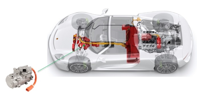
Figure 1: The electric compressor is the core component of the thermal management of electric vehicles
Electric compressors need to meet increasing demands, including lower cost, smaller size, less vibration and noise, higher power levels and greater energy efficiency. These requirements are inseparable from the design of the compressor drive circuit and the selection of excellent devices.
Motor compressor controller functions include: drive motor (inverter circuit: Including ASPM module or discrete device with gate drive, voltage/current/temperature detection and protection, power conversion), communication with the host (CAN or LIN, receiving start stop and speed signals, sending operating status and fault signals), onsemi has the corresponding solution in each circuit (Figure 1). This paper focuses on the ASPM module scheme of inverter circuit.
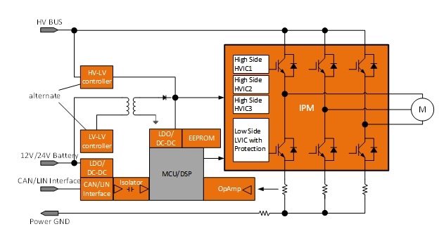
Figure 2: electric compressor drive circuit control block diagram
ASPM Automotive intelligent power module
The Automotive Smart Power Module (ASPM) is a modular solution that integrates power semiconductor devices, drive circuits and control circuits to provide efficient, reliable, and compact power conversion and control.
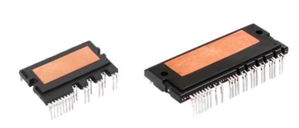
Figure 3: onsemi‘s ASPM27(left) and ASPM34(right)
Benefits of ASPM Automotive grade smart power modules
The ASPM module power chip and IC chip are welded directly to the copper pin frame, then covered with ceramic pin frame, and finally cast in epoxy resin. Compared with the discrete scheme, it greatly reduces the parasitic inductance, reduces the number of devices and the area required by the PCB board, provides high insulation and voltage resistance and can maintain good heat dissipation performance.
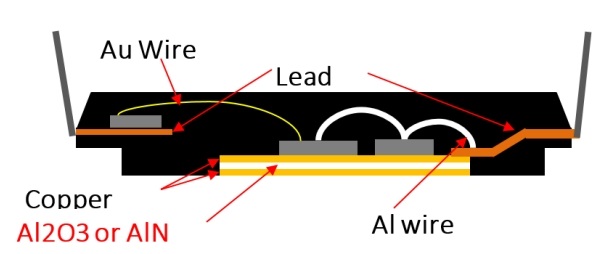
Figure 4: ASPM internal structure
1. Cost
In terms of cost, if the device costs of ASPM modules and discrete devices are compared separately, the cost of modules will be higher. However, in terms of the overall system cost, taking into account PCB, mechanical installation, quality and performance costs, the higher the system power, the use of ASPM modules will be more advantageous.
2. Thermal performance
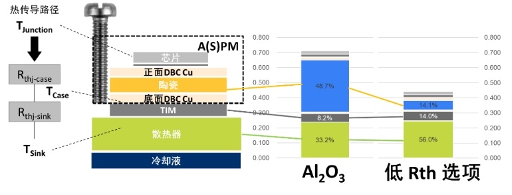
Figure 5: Thermal performance benefits of ASPM
In the design of electric compressor, the heat dissipation characteristic is a key factor, which directly affects the current carrying capacity of the module. Therefore, the thermal characteristics of the package are crucial in determining its performance. There are trade-offs between heat dissipation characteristics, package size, and isolation characteristics. The key to good packaging technology is to optimize package size while maintaining excellent thermal performance without sacrificing isolation levels.
Taking the 650V ASPM27 series as an example, these modules use DBC (copper clad) substrate technology, which brings good heat dissipation performance. The power chip is mounted directly on the DBC substrate, allowing heat to be more efficiently transferred from the chip to the outside, thereby improving heat dissipation efficiency and reliability, which is essential for maintaining the long-term stability and extended service life of the power module under high current operation.
Because the temperature directly affects the performance, reliability and life of the product, most designers want to know the temperature of the power chip accurately. However, because the power chip inside the package (such as IGBT, FRD) is operated under high pressure conditions, it is difficult to measure its temperature directly. In the past, due to cost and technical reasons, designers often did not directly measure the temperature of the power chip, but used an external NTC thermistor to detect the temperature of the module or radiator, although this method is simple, but can not accurately reflect the temperature of the power component itself. In the 1200V ASPM34 series, a major design innovation is to integrate the NTC thermistor and power chip on the same ceramic substrate to achieve temperature sampling inside the module. In this way, it can more accurately reflect the actual temperature of the power chip, so that developers clearly know the internal temperature margin of the module, and do the corresponding measures in the system control, such as at low speed, the system heat dissipation is not good, resulting in the module temperature is too high, you can appropriately increase the frequency, strengthen heat dissipation; Or reduce the frequency appropriately at high frequency and high power or overtemperature shutdown protection. With switching frequencies up to 20kHz (up to 40kHz for ASPM27-V3 and faster IGBT switching with lower switching losses for FS4), ON‘s ASPM modules can easily handle speed sampling requirements below 15,000 RPM for existing electric compressors.
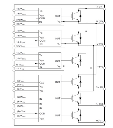
Figure 6: ASPM27 internal circuit block diagram
3. Power density
Compared with the discrete IGBT scheme, ASPM greatly reduces the inductance of the line without considering the electrical safety distance between the discrete devices. Up to 2500V insulation between the pin and the cooling surface, without the need to add additional insulation gaskets like IGBTs. And easy to install, high reliability.
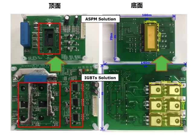
Figure 7: Power density of ASPM scheme compared with discrete IGBT scheme
4. Reliability
The ASPM module integrates the optimized protection circuit and the driver matching the IGBT switch characteristics, which can greatly reduce the circuit matching and development time for developers. By integrating undervoltage protection and short circuit protection, the system reliability is greatly improved. The built-in high-speed HVIC is resistant to dv/dt and negative pressure, providing an IGBT drive without optocoupler isolation. The integrated HVIC allows the use of single-power driven topologies that do not require a negative power supply.
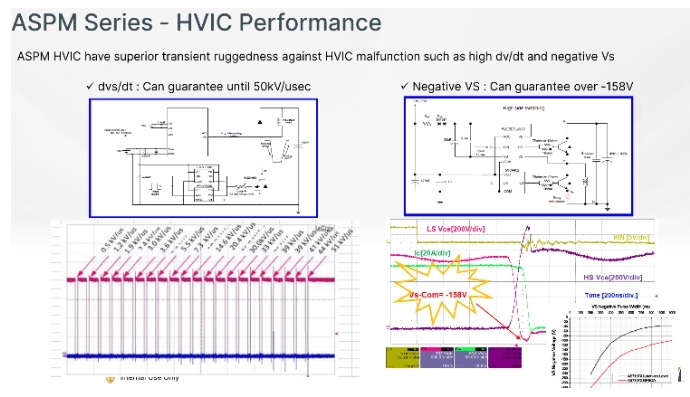
Figure 8: The HVIC is resistant to dv/dt and negative pressure
To achieve higher reliability, the mismatch of CTE between different materials can be minimized. On On‘s ASPM modules are AEC-Q and AQG324 certified, and discrete components are certified according to AECQ100/101. We can also consider some special reliability tests according to the specific requirements of customers.
Trends and challenges
The concept of margin needs to be taken into account when selecting power devices for electric compressors in high voltage environments to ensure that there is sufficient safety margin to cope with voltage fluctuations and transient events under various conditions.
The margin is usually based on several considerations:
1. Steady state voltage margin: under normal working conditions, taking into account voltage fluctuations, load changes and other factors, the design usually makes the actual operating voltage lower than the nominal voltage value of the power device, such as if the maximum voltage of the battery system is 400V, then the 650V voltage device provides a voltage margin of 250V.
2. Transient voltage margin: In the case of switching operation or power grid abnormalities, there may be instantaneous voltage spikes, and the margin is used to ensure that the device will not be broken down under these short but strong voltage shocks.
3. Reliability margin: During long-term operation, the voltage performance of the power device may gradually decline due to temperature, aging and other factors, so providing sufficient voltage margin helps to extend the life of the device and improve the reliability of the entire system.
When applied to systems with peak voltages close to their rated values, designers need to carefully evaluate whether the voltage margin is sufficient to ensure that the power device will operate safely and stably under all expected operating conditions. With the development of electric vehicle technology, the battery voltage platform continues to rise, and the peak voltage of some car companies‘ 400V platform has reached more than 500V, when the original 650V ASPM module is insufficient in new applications, it will promote the development of the market and technology to a higher voltage level such as 750V ASPM module.
In the 800V platform, due to the relatively small size of the passenger car compressor, the selection of 1200V module PCB design is relatively difficult, because the miniaturized compressor internal space is limited, the design of high voltage level PCB layout needs to ensure that there is sufficient electrical safety distance between the key components, which is a challenge for the high-density package of power modules. When the module works at high voltage, the loss is greater, and an efficient heat dissipation scheme is needed. The miniaturization design may limit the design of heat dissipation area and heat dissipation path, and increase the complexity of thermal management design. High voltage levels mean a higher risk of electromagnetic interference, requiring more detailed PCB wiring design and shielding measures to comply with relevant electromagnetic compatibility standards. It is also necessary to ensure that the insulation performance of the PCB meets the standards at high voltage levels to prevent problems such as creepage and breakdown. The line width, spacing, and number of layers required for high-voltage and high-current transmission can all increase, while reducing the influence of parasitic parameters such as inductance and resistance needs to be considered to optimize switching performance and reduce losses. In response to these challenges and needs, ON is about to launch the next generation of smaller size 1200V modules, integrated with the latest FS7 IGBT, to solve the above challenges, achieve more optimized performance, reduce the area by 36%, and also improve the insulation and voltage resistance characteristics, bringing more improvements to the design of electric compressor controllers.
Circuit design and PCB layout Tips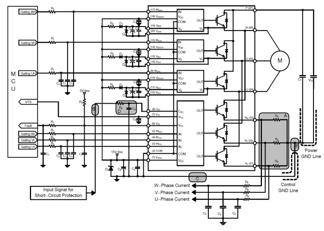
Circuit design and PCB layout Tips
Figure 9:650V ASPM27 series application circuit diagram
Graphic device parameter refer to 650 v ASPM27 car series intelligent power module application manual: https://www.onsemi.cn/download/application-notes/pdf/and9800-d.pdf.
Design suggestions for PCB layout:
Graphic device parameter refer to 650 v ASPM27 car series intelligent power module application manual: https://www.onsemi.cn/download/application-1. It is recommended that power ground and digital ground single-point grounding, grounding wire should be as short as possible and not too wide;
Graphic device parameter refer to 650 v ASPM27 car series intelligent power module application manual: https://www.onsemi.cn/download/application-2. The sampling resistance distance from Nu, Nv, Nw pins should be as short as possible to reduce the parasitic inductance caused by wire running;
Graphic device parameter refer to 650 v ASPM27 car series intelligent power module application manual: https://www.onsemi.cn/download/application-3.Csc protection of RC walk line should be short, and filtering capacitance to the best of receiving control rather than power;
Graphic device parameter refer to 650 v ASPM27 car series intelligent power module application manual: https://www.onsemi.cn/download/application-4.PN at the ends of the absorption capacity in the closer distance between modules, in IGBT Vce rush the better absorption effect;
Graphic device parameter refer to 650 v ASPM27 car series intelligent power module application manual: https://www.onsemi.cn/download/application-5. The bootstrap capacitor and voltage regulator should be placed in the nearest place from the module pin, and the electrical clearance and creepage distance requirements should be considered between each road; The charge and discharge of the bootstrap capacitor makes it itself a source of interference, and attention should be paid to the distance between it and other weak circuits that are easily interfered with;
Graphic device parameter refer to 650 v ASPM27 car series intelligent power module application manual: https://www.onsemi.cn/download/application-6. The module power supply capacitor should also be as close to the module pin as possible;
Graphic device parameter refer to 650 v ASPM27 car series intelligent power module application manual: https://www.onsemi.cn/download/application-7. The RC of the input control signal Vin should be close to the module pin, not the mcu, to ensure that the signal input into the module is clean.
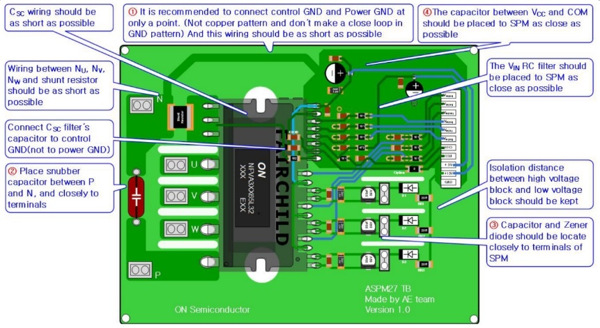
Figure 10:650 V ASPM27 PCB layout design
peroration
ASPM module is an ideal control device for motor control such as motor compressor and water pump. However, with the development of automotive batteries to higher voltages (such as the maximum battery voltage of more than 900V), and the efficiency requirements are getting higher and higher, the use of IGBT as a power device ASPM faces certain limitations. The same voltage specifications of the SiC device itself is much higher than that of the IGBT, and its switching loss is much lower than that of the IGBT device, which can adapt to the requirements of higher speed and higher efficiency.
|
Disclaimer: This article is transferred from other platforms and does not represent the views and positions of this site. If there is any infringement or objection, please contact us to delete it. thank you! |


 Business consulting

 13823761625
 Mail me