ACM6252 single-phase sine wave, square wave BLDC brushless motor drive IC solution
Time:2023-12-20
Views:457
introduction
Brushless DC motor is developed on the basis of brushless DC motor, which has advantages such as stepless speed regulation, wide speed regulation range, strong overload capacity, good linearity, long service life, small volume, light weight, and large output. It solves a series of problems existing in brushless motor and is widely used in various fields such as industrial equipment, instruments and meters, household appliances, robots, medical equipment, etc. Due to the lack of brushes for automatic commutation in brushless motors, electronic commutators are required for commutation. The function of this electronic commutator is achieved by the brushless DC motor driver.
There are currently three main control methods for mainstream brushless DC motors: square wave control (also known as trapezoidal wave control, 120 ° control, 6-step commutation control) and sine wave control, FOC (also known as vector frequency conversion, magnetic field vector orientation control). Shenzhen Yongfukang Technology Co., Ltd. is now vigorously promoting a single-phase sine wave/square wave DC brushless motor drive IC-ACM6252 The working voltage is 3.1V-18V and the working current is 1.2A, which can cover most small and medium-sized (<1A) fan and pump applications.
Product Introduction
ACM6252 is a single-phase brushless motor drive IC with an external Hall sensor. Internally integrated motor control algorithm and current detection, capable of controlling the silent/efficient rotation of single-phase brushless motors based on Hall signals. Internally integrated with 4 MOS chips less than 500m Ω, ensuring excellent thermal performance with a 1.2A current output. TSSOP-16 package, compatible with APX9230/M8121 pins; The periphery is extremely simple, with less than 10 resistors and capacitors
Product performance
•TSSOP -16 package
•Power supply voltage range: 3.1V-18V
•Output current: 1.2A
•Internal integrated Power FET conduction resistance: 500m Ω LS, 500m Ω HS
• Speed curve (multiple slope options/adjustable minimum/maximum speed)
•Soft start mode, no overcharging of starting current
•Sine wave or square wave drive, user configurable
•Flexible speed control method (customer optional):
Simulated voltage
PWM (duty cycle or frequency)
• Rich protection mechanisms: MOS overcurrent motor stalling, voltage overshoot, over temperature, undervoltage/overvoltage
• Minimalist peripheral: Minimalist only requires 4 resistors and capacitors
ACM6252 Application Information
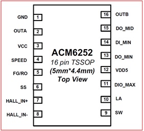
1. ACM6252 Pin Bitmap

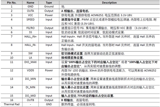
2. ACM6252 Pin Description

3. ACM6252 DEMO board schematic diagram

4. ACM6252 DEMO board PCB top-level design diagram
5. ACM6252 DEMO board PCB bottom layer design diagram
|
Disclaimer: This article is transferred from other platforms and does not represent the views and positions of this site. If there is any infringement or objection, please contact us to delete it. thank you! |


