


Do not let the USB voltage drop to slow down the charger
Time:2022-01-03
Views:2391
Portable devices such as mobile phones and tablets can charge faster than before. To obtain fast charging time, the voltage on the charger must be maintained at an appropriate level. If not, the charger may reduce the charging current to a lower (but still acceptable) level, eventually extending the overall charging time. A drop in voltage on the charging cable will result in insufficient voltage. Let‘s take a look at the impact this will have on universal serial bus (USB) cables and how to deal with possible problems.
A common USB cable interface has a contact resistance of about 30m Ω. Since there are four contacts (two at each end of the cable), this means that the total resistance is 0.12 Ω. Assuming that the length of each power cord is 1m and a standard 24awg cable is used, the total cable resistance is 0.166 Ω. The total resistance of cable and contact is expected to be 0.286 Ω. If the 5V converter is designed to provide an output current of 2.1a maximum, the expected voltage drop on the cable will be 0.6V. For a fixed converter voltage of 5.0V, the voltage at the end of the cable will drop to 4.4V. For USB devices, this voltage value is a lower voltage limit, and the cause of potential problems caused by high current load is obvious. Using a heavier USB cable will help, while an extra long USB cable with a smaller wire gauge cable will make the charging rate lower than the maximum. Some measures must be taken to further increase the charging current.
A common solution is to increase the no-load output setting voltage with a typical value of 5.0V to 5.15v to 5.20v as much as possible (the maximum value is 5.25V for USB 3.0). This solution provides sufficient (though still minimum) clearance at a maximum current of 2.1a. For higher load current, this method will soon be difficult to support.
Another method uses a dedicated charging port controller such as tps2511. This device monitors the USB data line and automatically provides the correct electrical signature to the charging compatible device; It also has a current limiting function. Its current sensing (/ CS) pin is pulled down to low level when the output current is half of the maximum current set by the current limiting threshold resistor.
As shown in Figure 1, connecting this pin to the feedback resistor of 5V power supply through a resistor (see Figure 33 in tps2511 data sheet) will increase the output voltage. This reduces the voltage drop by about 50%. For design examples, please refer to the reference design of dual port automobile USB charger.
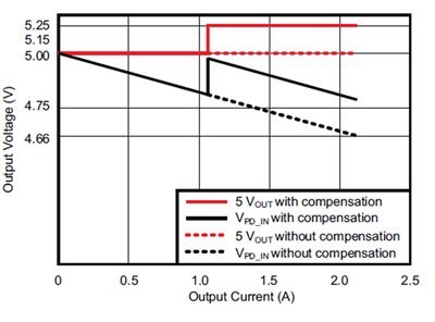
Figure 1: current sensing increases, increasing output voltage at 50% load to cope with voltage drop
The block diagram in Fig. 2 details a method of linearly increasing the converter output voltage to compensate for cable loss and keep the cable end voltage constant. This solution adds a sensing resistor to monitor the output current. A differential amplifier increases the voltage on the sensing resistor and uses this voltage to inject a current into the feedback (FB) pin of the controller. For further details on this method, see "power tips: compensating for voltage drop on cable
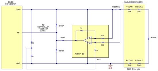
Figure 2: current sensing continuously adjusts feedback to maintain a stable voltage on the load
These technologies are just a few ways to deal with voltage drop and shorten charging time as much as possible.
|
Disclaimer: This article is transferred from other platforms and does not represent the views and positions of this site. If there is infringement or objection, please contact us to delete. thank you! |


 Business consulting

 13823761625
 Mail me