


How does the Boost circuit boost voltage? How is BUCK circuit depressurized?
Time:2024-06-14
Views:55
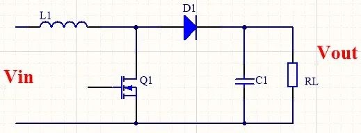
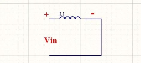
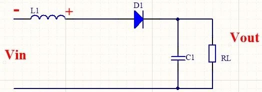
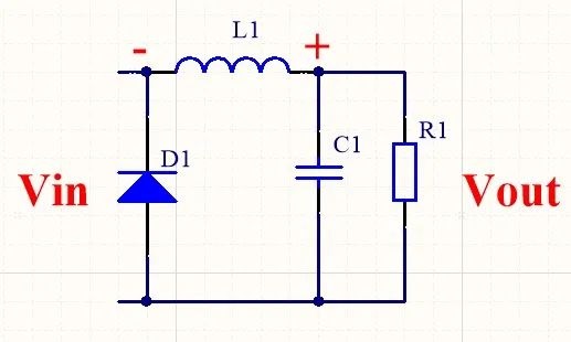
How is the Boost circuit boosted
The basic Boost circuit is shown in the figure
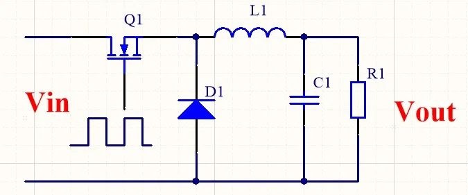
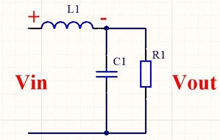
How is BUCK circuit depressurized
|
Disclaimer: This article is transferred from other platforms and does not represent the views and positions of this site. If there is any infringement or objection, please contact us to delete it. thank you! |


 Business consulting

 13823761625
 Mail me