


How to calculate CAN special baud rate
Time:2024-05-08
Views:141
CAN bus adopts asynchronous serial communication, that is, there is no separate clock line to ensure the consistency of the clock between each transceiver, each transceiver is according to the pre-set baud rate to the level on the bus. Therefore, the accurate baud rate setting is very important for the stable communication of CAN bus.
In CAN bus, we CAN realize the communication of different baud rates by controlling the bit timing register in CAN node. The CAN protocol divides a bit time into synchronization segment, propagation segment, phase buffer segment 1 and phase buffer segment 2. The time length of each segment can be expressed as a base time unit of an integer, which is obtained by frequency division of the system‘s clock oscillator.
The synchronization segment is located at the starting position of a bit, and CAN-bus stipulates that the jump edge is the synchronization signal. However, there is a network propagation delay between the sending node sending a bit and the receiving node receiving this bit, and the propagation segment is to compensate for this propagation delay. Since the sampling point is located between phase buffer segment 1 and phase buffer segment 2, By setting the values of phase buffer segment 1 and phase buffer segment 2, the position of the sampling points can be adjusted to ensure that each bit sampling point is consistent. The length adjustment range of the buffer segment is determined by the synchronous jump width (SJW).
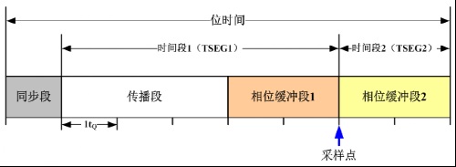
FIG. 1 CAN time structure diagram
After a simple understanding of the segmentation of the CAN bus bit time, let‘s look at how to set the baud rate of a node. Figure 2 shows the CAN bit time characteristic register (CAN_BTR) of an ARM kernel.

FIG. 2 Structure diagram of the bit time characteristic register in an ARM kernel
SILM (silent mode) and LBKM (loop mode) are used for debugging;
SJW: synchronous jump width;
TS2/TS1: indicates the allocation of two time segments in the bit time.
BRP: Baud rate divider, this region defines the length of the basic time unit;
For example, a well-known automobile factory CAN communication standard stipulates that when the communication rate is 125 kbps, a single sample should be used, and the sampling point position is set between 70% and 77%. The values of the bit timing parameters are shown in Table 1 and Table 2.
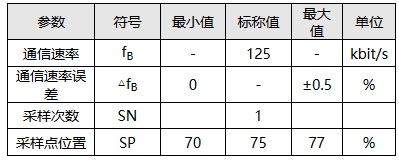
Table 1 LS_CAN communication rate and sampling point parameters
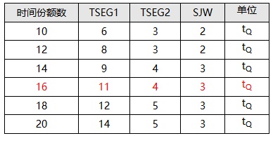
Table 1 LS_CAN communication rate and sampling point parameters
Table 2 LS_CAN optional time share and synchronization jump bandwidth
Sampling point: The sampling point can not be too far forward or too far back, otherwise if it is just in the rising or falling edge of a bit, it will cause identification errors, so according to the CIA105 specification, the sampling point is about 87.5%. But generally we can choose between 75% and 85% according to the actual situation;
Synchronization jump width (SJW) : The value of SJW directly affects the adjustable range of phase buffer segment during resynchronization, and the value of SJW can be selected between 1 and 4. We choose 3 and 4 to make the bus obtain a wider baud rate tolerance;
Sampling times: divided into single sampling and triple sampling, triple sampling at the beginning of the design is to filter out the burr on the bus, but the use of triple sampling often affects the SJW jump, so we generally use single sampling in practical applications.
After understanding the principle of setting baud rate, we adopted the baud rate calculation software of ZLG to calculate the setting parameters of 25kbps baud rate, and the calculation results are shown in Figure 3.

FIG. 3 Calculation parameters of 25kbps baud rate
According to the above principles, we select a set of parameters whose sampling point is 75%, SJW is 4, and time share is 14, and adopt ZLG‘s CAN card for verification.
l Automatic baud rate identification: The baud rate of CAN card is identified using the function of CANScope automatic detection of baud rate, and the recognition result is 25kbps;

Figure 4 Automatic detection of baud rate
l Sampling point test: CANScope was used to test the sampling point of CAN card at the current baud rate, and the test result was 75%;
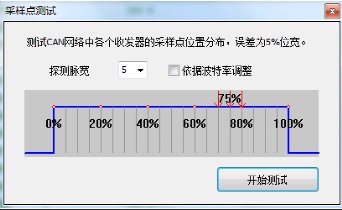
Figure 5 Sampling point test
l bit width tolerance test: CANScope was used to test the bit width tolerance of CAN card at the current baud rate, and its tolerance to baud rate was tested. The test results ranged from 24kbps to 26kbps, indicating a good tolerance.

Figure 6-bit tolerance test
L-bit time test: The CANScope eye map function is used to test the bit time of the CAN card at the current baud rate. The bit time is 40us, which is consistent with the bit time of 25kbps baud rate.
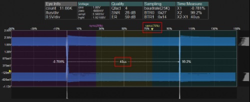
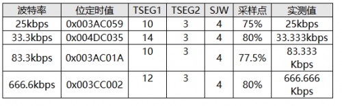
Figure 7 Eye map test bit time
Through the verification of the baud rate register parameters calculated by the Baud rate calculator, it is found that the test results are consistent with our expected results, so when using the special baud rate calculator, we can quickly calculate the parameter value of the bit timing register. Here we give some reference to the special baud rate parameters:
|
Disclaimer: This article is transferred from other platforms and does not represent the views and positions of this site. If there is any infringement or objection, please contact us to delete it. thank you! |


 Business consulting

 13823761625
 Mail me