


Three-phase motors: Types and working principles
Time:2024-04-29
Views:143
Three-phase motors are widely used in the industry and play a vital role in various industries. Therefore, it is very important to know and understand how they operate.
The squirrel cage induction motor is known for its simple design, which uses a stator winding to generate a rotating magnetic field. The synchronous speed that determines the motor speed depends on the power supply frequency and the number of stator poles. Wire-wound rotor induction motors allow for variable speed via a three-phase rheostat, but wire-wound rotor motors have become less popular due to maintenance issues. The synchronous motor uses a DC powered rotor, which can maintain a constant speed under different loads as long as the correct starting procedure is followed.
Squirrel-cage induction motors, wire-wound rotor induction motors and synchronous motors will be studied in more detail in this paper.
Squirrel cage induction motor
The motor widely used in industry is the three-phase squirrel-cage induction motor. The squirrel cage motor in Figure 1 has two parts: a rotor and a three-phase stator. The term "armature" refers to a rotating part consisting of a winding and a commutator, while the term "rotor" refers to a rotating part of a motor that does not contain a winding. Note the identification of the motor leads labeled T1, T2, and T3. The simple design is one of the attractive features of the squirrel cage motor.
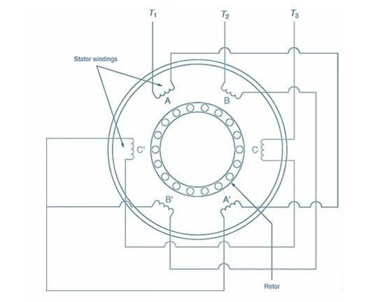
Figure 1. Squirrel-cage induction motor. Image courtesy of Amna Ahmad The rotor of a squirrel cage motor has no winding. Instead, it consists of metal strips attached to each end-to-end ring. Between the metal strips are laminated metal plates. During the operation of the motor, a voltage is induced in the metal strip, which generates an electric current and a magnetic field. In fact, the squirrel cage motor is named after this rotor, which resembles the exercise wheel commonly found in mouse and hamster cages.
Figure 2 illustrates a three-phase AC power supply applied to the stator winding. A three-phase power supply produces a peak voltage every 120°.
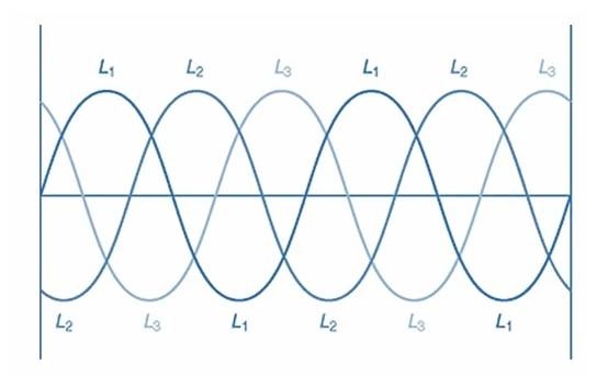
Figure 2. Three-phase waveform. Photo courtesy of Amna Ahmad
Now, notice the three separate phase windings in the stator in Figure 3. Phase windings are arranged sequentially around the stator housing. When the applied three-phase power peaks on the square side of the T1 phase, the phase windings T2 and T3 will have opposite polarity, and their values will be between 0 and their negative values. When the T2 phase peaks in its positive direction, T1 and T3 will have opposite polarity, and their values will be between 0 and negative. This pattern persists for the entire 360° rotation of the applied AC sine wave.
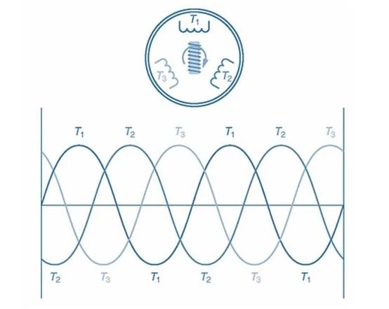
Figure 3. Phase rotation creates a rotating magnetic field in the stator. Image courtesy of Amna Ahmad A rotating magnetic field appears around the stator. The speed at which the rotating magnetic force rotates is the synchronous speed. The synchronization speed is affected by the number of stator poles and the frequency of the applied alternating current. This relationship can be illustrated by the following formula:
S=120×fP
S = Synchronization speed (rpm)
F = Frequency of the applied alternating current in Hertz (Hz) P = number of stator poles
For example, what is the synchronization speed of a four-pole squirrel cage motor running on 60 Hz AC power?
What values are known?
F is equal to 60 Hertz
P = 4
What value is not known?
S = ?
What formula can I use?
S=120×fP=120×604=1800rpm
Therefore, the synchronous speed of the cage motor is 1800 revolutions per minute.
The stator‘s rotating magnetic field induces a voltage in the rotor guide bar, which generates an electric current. The current in the rotor guide bar creates another magnetic field, which is attracted by the rotating magnetic field in the stator, causing the rotor to turn and creating torque. However, the rotor does not rotate at the same speed as the stator‘s rotating field. Friction and wind resistance (wind resistance) in the bearing will cause the rotor to rotate at a slightly slower speed. This is called rotor slip. Rotor slip is the speed difference between synchronous speed and rotor speed.
Until recently, squirrel cage motors were considered constant speed motors. As can be seen from the synchronization speed formula above, the way to change the speed of the motor is to change the frequency of the applied AC voltage or change the number of poles of the motor. American Electric Power maintains the power line frequency accurately at 60 Hz. Therefore, changing the frequency of the applied AC power supply is not an option. It is also impossible to change the number of poles of the motor. The engine had to be completely rebuilt. Nowadays, however, with electronic variable speed drives, the frequency of the applied AC power can be changed, and therefore the speed of the squirrel cage motor can also be changed. Using solid-state components, electronic variable speed drives accomplish this by converting the applied alternating current into direct current, chopping the DC into pulses of variable frequency, and converting these pulses into artificial alternating current, which is then applied to the motor. Now, the frequency of the applied AC power supply can be changed, allowing the motor to operate at a variable speed.
To reverse the rotation direction of a squirrel-cage motor, simply swap the connections of any two of the three stator leads. Usually, T1 and T3 are interchangeable. This will cause the rotating magnetic field in the stator to rotate in the opposite direction. The rotor will turn in the new direction of the rotating magnetic field, which is opposite to the original direction.
Squirrel cage induction motor applications
Squirrel-cage induction motors are widely used in many industries due to their robust construction and reliability. An important application is in industrial machinery, where they power pumps, compressors and conveyors, providing the torque and speed needed for efficient operation. In addition, these motors are often integrated into HVAC systems in large commercial buildings and industrial facilities, ensuring proper ventilation and climate control.
In addition, by connecting the squirrel cage induction motor to the grid, it can be reused as a generator. In this setup, when the motor shaft is turned manually or by an external force, an electromotive force (EMF) is generated in its windings due to the phenomenon of electromagnetic induction. This electromotive force produces an AC output that can be fed into the grid power supply, effectively converting mechanical energy into electrical energy. The application is particularly useful in emergency situations where backup power, remote areas where grid connections are unreliable, or where continuous power supply is critical.
Winding rotor induction motor
A variant of the squirrel cage motor is the winding rotor induction motor. The motor is designed to meet the needs of variable speed three-phase motors. However, with the increase in the use of electronic variable frequency drives, it is becoming less common.
The winding rotor induction motor consists of a rotor with winding, a slip ring, a brush and a three-phase stator. Figure 4 shows the components of a winding rotor induction motor. Note the identification of the motor leads, where the stator connections are labeled T1, T2, and T3 and the wound rotor connections are labeled M1, M2, and M3. Figure 4 also shows the three-phase rheostat connected to M1, M2, and M3 in the rotor circuit.
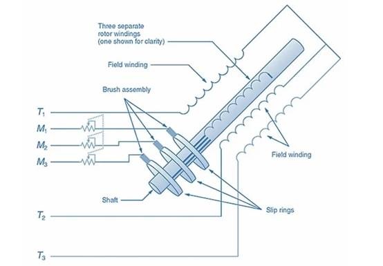
Figure 4. Components of a winding rotor induction motor. For clarity, only one winding is shown on the rotor shaft. Picture provided by Amna Ahmad three-phase power supply applied to the stator windings. A rotating magnetic field is generated to induce voltage into the three-phase rotor windings. This induced voltage generates a current, which creates a magnetic field in the rotor windings. The magnetic field of the rotor interacts with the rotating magnetic field of the stator, causing the rotor to rotate. By changing the three-phase rheostat, the strength of the rotor magnetic field can be changed. If the magnetic field weakens, the rotor will slow down. When the magnetic field is strengthened, the rotor speed increases.
This control of the rotor magnetic field can be used to change the speed of the wound rotor induction motor when driving a constant load. In addition, the rotor magnetic field can be changed through an automated process in response to changing load conditions. In this way, the speed of the wound rotor induction motor can be kept fairly constant.
To reverse the rotation direction of the winding rotor induction motor, it is only necessary to exchange the connections of any two of the three stator leads. Usually, T1 and T3 are interchangeable. This causes the rotating magnetic field in the stator to rotate in the opposite direction. The rotor then turns in the new direction of the rotating magnetic field, which is opposite to the original direction.
Winding rotor induction motors also have disadvantages. It is more expensive than similarly sized squirrel-cage motors, requires more maintenance due to brush and slip ring wear, and while it offers variable speed, this benefit becomes less attractive due to the use of drives.
Application of winding rotor induction motor
Wire-wound rotor induction motors are versatile and controllable, making them ideal for demanding applications. One notable use is cranes and hoists in the manufacturing and construction industries, where speed and torque control is essential for safe and efficient lifting operations. In addition, these motors are commonly used in mining equipment to perform heavy duty tasks, such as driving conveyor belts and powering drilling RIGS. In addition, they are an integral part of large pumps and fans that require variable speed control, ensuring performance and energy efficiency in industrial processes.
Synchronous motor
A synchronous motor (shown in Figure 5) has a three-phase stator, a winding rotor, a slip ring, and a brush. However, in contrast to the three windings of a wire-wound rotor induction motor, the rotor has a single winding. The rotor also contains a short circuit rod similar to the rotor of a squirrel cage motor. Synchronous motor leads are labeled T1, T2, and T3 for stator connections, and R1 and R2 for rotor connections. Dc power supplies the rotor.
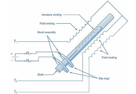
Figure 5. Components of synchronous motor. Note the direct current applied to the rotor winding. Photo courtesy of Amna Ahmad Synchronous motors are started by applying a three-phase power supply to the stator. However, the rotor is not energized at this time. When a three-phase power supply is applied to the stator, a rotating magnetic field is generated. The rotating magnetic field induces a voltage in the short-circuit rod of the rotor. This induced voltage generates a current, which creates a magnetic field in the rotor. The rotor is then attracted by the stator‘s rotating magnetic field, causing the rotor to rotate.
When the rotor reaches speed, the DC power supply is energized, thereby applying direct current to the rotor winding. This causes the rotor to act as an electromagnet. The rotor is now locked in sync with the stator‘s rotating magnetic field. This allows the synchronous motor to operate at a constant speed from no-load to full-load conditions. An important rule to remember is that a synchronous motor should never be started with direct current applied to the rotor windings. If the synchronous motor is started in this way, the rotor will not be able to turn, thus damaging the rotor and the DC power supply.
To reverse the rotation of the synchronous motor, simply swap the connections of any two of the three stator leads. Usually, T1 and T3 are interchanged, causing the rotating magnetic field in the stator to rotate in opposite directions. The rotor then turns in the new direction of the rotating magnetic field, which is opposite to the original direction.
Synchronous motor application
Synchronous motors play a key role in applications that require speed control and synchronization with power systems. Their notable application is in power plants, where they are used as synchronous generators to generate electricity in an efficient, stable manner. In the Marine industry, these motors power a ship‘s propulsion system, providing efficient and responsive performance for navigation. In addition, synchronous motors are used in high-performance industrial machinery such as compressors and centrifugal pumps, where speed regulation is crucial for operation and energy saving.
|
Disclaimer: This article is transferred from other platforms and does not represent the views and positions of this site. If there is any infringement or objection, please contact us to delete it. thank you! |


 Business consulting

 13823761625
 Mail me