


Yizhao solves the problem of strange frequency points exceeding the standard
Time:2023-12-07
Views:491
Authors: Wei Xuemei and Fang Xinjie
1 preface
In the rapidly developing digital era, the frequency of clock signals in circuits is also increasing. Due to the narrowband spectrum of clock signals exhibiting energy concentration in the spectrum, this often brings great difficulties to our products for EMI testing. In addition, there may also be some unexpected clock like interference on the circuit, manifested as narrowband peaks in the spectrum, which is confusing. In this issue, the editor will discuss with you how to deal with the strange clock like frequency radiation problems in circuits.
II Case Introduction
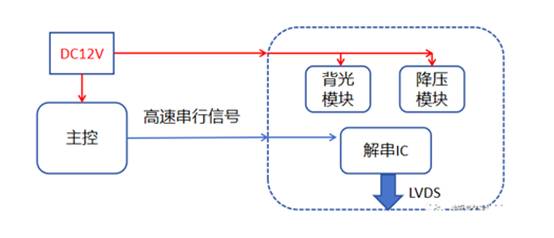
The customer‘s product is a display screen driver circuit that decodes the high-speed serial signal transmitted from the main control and then transmits it to the display screen. The main module is divided into three parts. One is the backlight boost module, which is used to power the backlight with a switching frequency of 2.2MHz. The other is the boost module, which supplies power to the deserialized IC with a switching frequency of 500KHz. The other is the signal deserialization module, which outputs an LVDS clock frequency of 48MHz after deserialization. The simple circuit framework is as follows:
III Review of rectification process
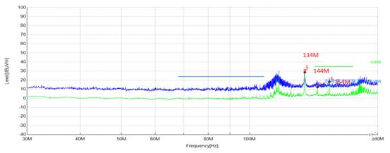
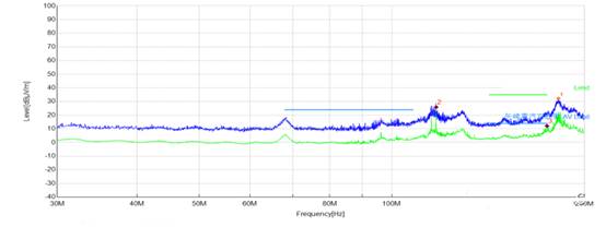
3.1. Test data
From the above data, it can be seen that there are frequency points with a 10MHz interval, and they exceed the standard at the 154MHz frequency point.
3.2. Analysis
Throughout the entire circuit board, the PWM frequencies of the switching power supply are 500KHz and 2.2MHz, respectively. The output clock of the deserialization chip is 48MHz, and there is no frequency of 10MHz or related integer multiples.
Conjecture 1: This frequency may be on the control side, because during testing, the control is also working and conducting tests in the same dark room;
Conjecture 2: This frequency is on the driver circuit side, possibly due to the clock generated during internal operation of the chip, radiating outward through a certain path.
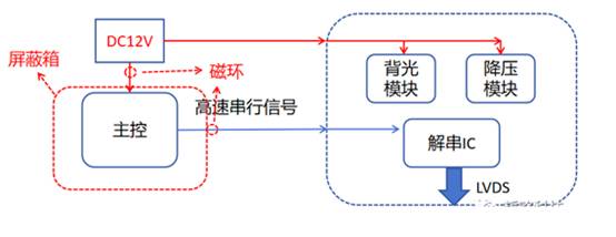
Regarding conjecture 1: By placing the main control part in a shielding box and adding magnetic ring filtering tests to the main control signal and power lines, the possible spatial radiation and wiring harness radiation paths of the main control were blocked. After testing, it was found that the corresponding frequency points did not improve, indicating that the problem is not in the main control part.
Regarding conjecture 2: if the power supply to the driver circuit board is disconnected and the frequency point disappears, it indicates that the frequency point exists on the driver circuit board.
3.3. Problem positioning and countermeasures
Through analysis, it can be located that the problem lies in the driver circuit board. Next, it is necessary to confirm which module is causing the problem.
Conjecture 1: Backlight module
Conjecture 2: Voltage Reduction Module
Conjecture 3: Unstring IC
Due to the presence of three modules, we need to investigate them one by one, using three methods:
(1) Find the corresponding chip manual and see if it mentions the relevant frequency;
(2) Using a spectrograph to locate problems;
(3) Disconnect each module one by one for verification.
The first method of checking the specification book did not find the relevant frequency points, while the second method is the most convenient. However, since we do not have a spectrograph at hand, we can only use the third method to troubleshoot the problem.
Prioritize the backlight module as it does not affect the operation of the other two modules. The first step is to pull down the backlight enabled foot, which is ineffective; Step 2, in order to completely turn off the backlight module, disconnect the backlight input power and the frequency point will disappear.
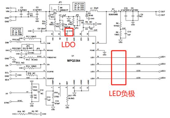
Now we can pinpoint the problem point as the backlight module. Although we don‘t know the operating mode inside the chip, we can suppress noise radiation through peripheral filtering. The following is a recommended circuit diagram for the boost chip:
Due to the inability to determine which pin has noise, we first focus on pins with long wiring and pins that do not affect functionality even with filtering, such as LED negative wiring and LDO output pins. In actual operation, we added 1nF capacitor filtering to the LDO output pin, and added magnetic beads and capacitor secondary filtering to the LED negative pin, which has a significant effect. The data after rectification is as follows:
It can be seen that the previous frequency points of 134MHz, 144MHz, and 154MHz are no longer obvious.
IV summary
Clock problem is one of the most concerning issues in the EMC field. Dealing with clock problems requires attention to the source of the clock signal, clock doubling, possible radiation paths, coupling paths, etc., in order to have a clear understanding. Sometimes we have to face some strange frequency points, and it is impossible to know where the source is simply from the circuit. In such cases, it is even more necessary to calmly investigate and rectify EMC problems. Isn‘t it just attention to detail and patience?
|
Disclaimer: This article is transferred from other platforms and does not represent the views and positions of this site. If there is any infringement or objection, please contact us to delete it. thank you! |


 Business consulting

 13823761625
 Mail me