


How to select the LC filtering inductor for the output of Class D power amplifier IC
Time:2023-12-03
Views:526
1.Overview of Class D output inductance function
Usually, in high-power Class D amplifier applications with an output power of over 10W, LC filtering is required at each output end. The parameter selection of this LC filtering circuit is crucial for whether the Class D amplifier can achieve the designed audio performance, efficiency, and EM/EMI requirements. This article analyzes the selection of LC inductors in the design of Class D power amplifiers, hoping to provide assistance and guidance for achieving the design goals of power amplifier systems.
 In the above figure, the green waveform represents the current flowing through the inductor, and the yellow waveform represents the PWM waveform output by the audio power amplifier.
 .
.
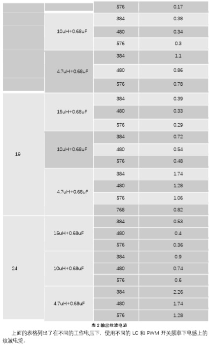
 Taking a horn with a DC resistance of R as an example (without considering the different impedance of the horn at different frequency points, assuming that all frequency points are 4ohm; and also without considering the Rdson of the power amplifier, inductance, and DCR of the wire), without limiting the output power of the power amplifier, the maximum horn current is PVDD/R. If PVDD=19V, Load=4ohm, LC filter is selected as 10uH+0.68uF, PWM switching frequency is 480kHz, and modulation mode is High Performance Mode, according to the analysis above and Table 2 of ripple current measurement, the maximum possible current flowing through the inductor is
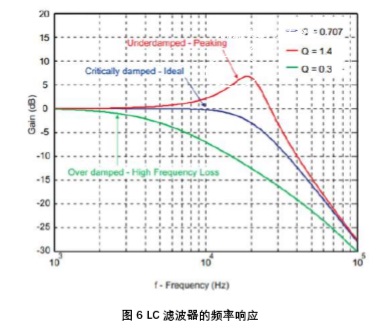
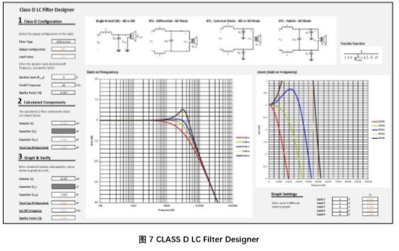
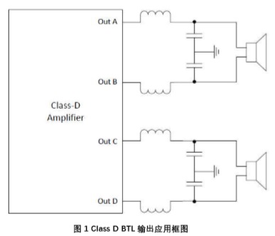
Figure 1 shows a typical BTL output application diagram for Class D
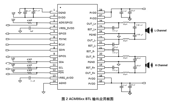
Figure 2 shows the typical BTL output application diagram of ACM86xx digital power amplifier
In the typical application of the ACM86xx series digital input audio power amplifier in the above figure, a 10uH+0.68uF output LC filtering circuit is generally selected. In many practical situations, users will follow the reference diagram to select a 10uH inductor. However, due to the different output power, amplifier operating voltage, and speaker load, many users may overlook or doubt the requirements of inductor current, resulting in abnormal operation of Class D amplifiers. Below, this article mainly analyzes and discusses the selection of inductance current.
2. Composition of Class D output inductor current
2.1 Starting current
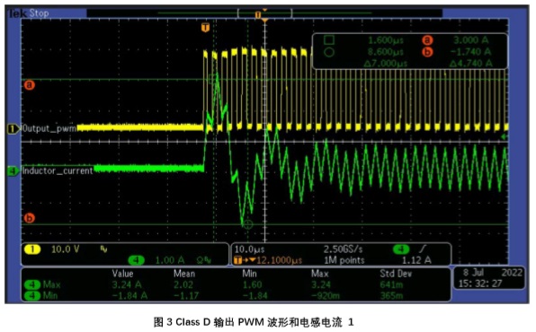
Class D amplifiers are modulated by PWM (audio signals are modulated at higher PWM frequencies). Taking conventional PWM modulation as an example, the single-sided output common mode voltage is PVDD/2 (i.e., the output duty cycle is 50%), and an oscilloscope and current probe are used to measure the current flowing through the output inductor at the moment of power amplifier startup, as shown in the following figure:
In the above figure, the green waveform represents the current flowing through the inductor, and the yellow waveform represents the PWM waveform output by the audio power amplifier. The power supply voltage of the amplifier is PVDD=24V, and the output LC (inductor is 10uH, capacitor is 0.68uF) starts the common mode voltage establishment moment, and the output current reaches about 3.2A. Peak current during power on startup
Ipstart =PVDD * Duty *((C/L)^0.5)*SIN(0.5*pi)
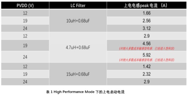
Here, PVDD is the PWM output Duty Cycle when the power supply voltage of the amplifier is Duty without input signal, i.e. the duty cycle. The table below lists the current on the inductor when different LC filters are powered on and started under different power supply voltages:
Here, PVDD is the PWM output Duty Cycle when the power supply voltage of the amplifier is Duty without input signal, i.e. the duty cycle. The table below lists the current on the inductor when different LC filters are powered on and started under different power supply voltages:
Summary:
1) For inductor selection, the first thing to avoid is the inability to start due to excessive power on current (triggering overcurrent protection upon power on).
2) In many cases, the current output on the horn line during normal operation may be very small, less than 2A. However, if the inductance value is selected too small, there may be a situation where the establishment process of the startup common mode voltage exceeds 2.5A, leading to overcurrent protection of the power amplifier.
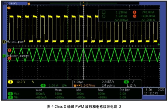
2.2 Output ripple current
Class D power amplifiers are modulated by PWM (audio signals are modulated at higher PWM frequencies). Taking conventional PWM modulation as an example, when the output common mode is stable, the inductance ripple is basically stable.
The power supply voltage of the amplifier is PVDD=24V, with an output LC (inductance of 10uH and capacitance of 0.68uF) and a PWM switching frequency of 480kHz.
The higher the switching frequency, the smaller the ripple current, the larger the inductance, and the smaller the ripple current. To reduce the switching loss of audio amplifiers, it is recommended to use a switching frequency of 480kHz. Therefore, it is generally recommended that the inductance value should not be lower than 10uH in applications with PVDD greater than 12V.
. The table above lists the ripple current on the inductor at different operating voltages and switching frequencies of LC and PWM.
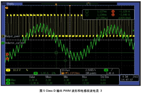
2.3 Horn current superimposed ripple current
After the power amplifier is turned on, the current flowing through the inductor during music playback includes the maximum current of the speaker line and the ripple current.
The following figure shows the current waveform measured on the inductor during actual music playback:
Imax=PVDD/R+ripple current=19/4+0.54=5.29A
3. LC filter characteristics
After selecting the appropriate inductance based on power supply voltage, speaker load, output power, etc., it is also necessary to pay attention to the impact of LC filters on the frequency response of audio signals. In addition, the impedance of the horn can also affect the frequency response characteristics of the filter. So, when selecting LC parameters, it is also necessary to consider the impedance of the horn used. Ideally, choose a suitable LC to form a critical damped, flat passband, and good phase response filter. At the same time, attention should also be paid to the cutoff frequency and quality coefficient Q of the LC filter.
The following figure shows the frequency response curve of a typical LC filter:
For the convenience of users, ACME provides an LC filter frequency response search tool. Users only need to input the speaker impedance, inductance, and capacitance parameters to obtain the frequency response curve of the LC filter, in order to confirm whether the LC options meet the requirements of audio design. If you need this tool, you can contact ACME to obtain it. As shown in the following figure:
4. Summary
In high-power Class D power amplifier applications with an output power of over 10W, LC filtering is required at each output end. The parameter selection of the LC filtering circuit is crucial for whether the Class D amplifier can meet the designed audio performance requirements. At the same time, the LC filtering circuit can also affect the efficiency of the amplifier system and the hardware EMI/EMC characteristics. This article first describes the inductance function of the LC filter in the design of Class D power amplifiers, the composition of inductance current, including the starting current of Class D power amplifiers, inductance ripple current, and horn current superimposed ripple current. Provide reference for selecting appropriate LC parameters through some actual measurement data. Finally, the frequency response characteristics of LC filters are also factors that need to be considered in audio design using Class D amplifiers.
|
Disclaimer: This article is transferred from other platforms and does not represent the views and positions of this site. If there is any infringement or objection, please contact us to delete it. thank you! |


 Business consulting

 13823761625
 Mail me