


Design of High Fidelity Headset Amplifier Based on SRPP Circuit of Electron Tube
Time:2022-12-24
Views:1433
1 Introduction
In the high fidelity audio circuit, the electronic tube amplifier has been loved and concerned by the vast number of audio enthusiasts because of its unique charm and musical sense. In recent years, high fidelity earphones are favored by more and more music lovers and audio enthusiasts because of their convenience and relatively low price. In the high fidelity earphone family, the earphone impedance is distributed from low resistance, medium resistance to high resistance: for example, the rated impedance of Aiji 271S is 48 Ω, the rated impedance of Baya Power Dt48 is 200 Ω, and the rated impedance of SenHaier HD580, HD600, and HD650 is 300 Ω. For earphones with high impedance, special supporting circuits are usually required to show their excellent performance. Compared with the loudspeaker unit used for the loudspeaker, the earphone has more strict requirements on the performance indicators of its drive circuit. Compared with transistors, electronic tubes have high static operating point voltage, large internal resistance, and are more suitable for outputting driving signals with large swing and small current. This feature makes the electronic tube suitable for driving high fidelity earphones with high quality requirements but low power requirements.
In the high fidelity audio circuit, the electronic tube amplifier has been loved and concerned by the vast number of audio enthusiasts because of its unique charm and musical sense. In recent years, high fidelity earphones are favored by more and more music lovers and audio enthusiasts because of their convenience and relatively low price. In the high fidelity earphone family, the earphone impedance is distributed from low resistance, medium resistance to high resistance: for example, the rated impedance of Aiji 271S is 48 Ω, the rated impedance of Baya Power Dt48 is 200 Ω, and the rated impedance of SenHaier HD580, HD600, and HD650 is 300 Ω. For earphones with high impedance, special supporting circuits are usually required to show their excellent performance. Compared with the loudspeaker unit used for the loudspeaker, the earphone has more strict requirements on the performance indicators of its drive circuit. Compared with transistors, electronic tubes have high static operating point voltage, large internal resistance, and are more suitable for outputting driving signals with large swing and small current. This feature makes the electronic tube suitable for driving high fidelity earphones with high quality requirements but low power requirements.
2 Input stage
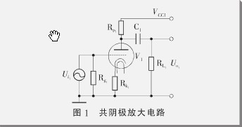
The input stage adopts a common cathode amplifier circuit composed of an electron tube triode, and its circuit schematic diagram is shown in Figure 1. The resistors RL1, Rk1 and Rg1 in the figure are respectively connected with the anode, cathode and grid of the electron tube, so that the electron tube can establish a stable working point, with appropriate gain and appropriate local negative feedback. V1 can choose a commonly used electronic triode, such as the single triode ECC92, or one of the double triodes ECC82, 12AU75814, etc. The working principle of the triode is different from that of the bipolar triode in the transistor, but similar to the field-effect transistor, it belongs to a voltage type amplifier, and its main parameters are transconductance gm, internal resistance rp and amplification factor μ, And the three meet:

The slightly variable equivalent circuit of the circuit is shown in Figure 2. Here, the electron tube is regarded as a controlled voltage source. In the figure, the input voltage can be expressed as:
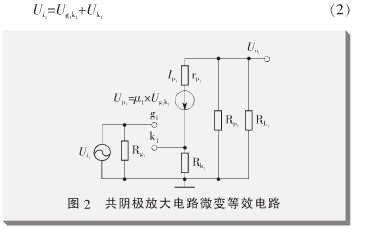
In formula (2), Ug1k1 is the voltage at both ends of the grid and cathode of the electron tube, and Uk1 is the voltage at both ends of the cathode resistance Rk1:
3 Output stage
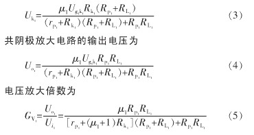
The output stage adopts SRPP circuit. The electronic tube can select either the triode with appropriate internal resistance, such as 6N6 and E182CC, or the low-power pentode for power amplifier, such as 6P15, 6P14, EL42, EL91, EL84, and EL86.
Generally, the pentode has large internal resistance and high gain. In order to reduce the output impedance and gain, the pentode should be connected to a triode for use.
The output stage in this paper selects a low-power pentode as the amplifier. When selecting other types of tubes, it is necessary to determine the parameters of the peripheral components and the power supply voltage VCC2 according to the tube‘s own parameters. In Figure 3, Rsg1 and Rsg2 connect the second gate and anode of pentode V2 and V3 respectively, thus becoming the triode working mode. Rk2 and Rk3 are respectively connected with the cathodes of V2 and V3 to provide proper grid negative pressure for the electron tube. RL2 represents the impedance of the load. Different types of tubes are selected. Due to the difference in internal resistance and gain, different sound performances will occur when driving earphones. Generally, the selection of tubes can be determined through subjective sound quality evaluation.
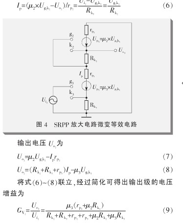
Figure 4 is the slightly variable equivalent circuit of Figure 3, where Ip is:
Apply a voltage U ′ o2 at the output terminal, and then the current from the output terminal to the inside is recorded as I ′ o2, which can be calculated by Formula (10)~(12):
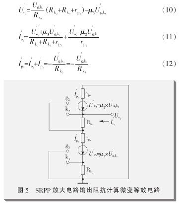
From equations (11)~(13), it can be calculated that the output impedance of SRPP amplification circuit is:
4 Overall design
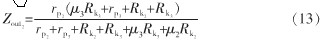
The circuit schematic diagram of the whole machine and the values of components are shown in Figure 6.
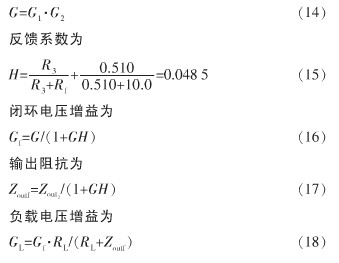
The input stage amplifier uses Ecc82 double triode, and the output stage uses 6P15. The basic parameters are shown in Table 1. In order to reduce the output impedance and match the earphones with low impedance, the SRPP circuit at the output stage works in parallel with two tubes. The relevant parameters of the amplifier are calculated as follows, where the open-loop voltage gain is:
.jpg)
5 Test results
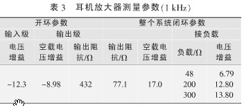
After the test, when the headphone amplifier drives different impedance loads, the parameters in the circuit are shown in Table 3. It can be seen from Table 2-3 that the measured results are close to the theoretical calculation results. Compared with the general transistor earphone amplifier, the output impedance of the tube amplifier is slightly higher. This impedance will affect the total Qt value of the earphone unit, so as to affect the transient characteristics of the earphone, which is also a factor in the unique auditory effect of the tube earphone amplifier.
It can be felt from the actual listening that the amplifier has sufficient dynamic range, the medium frequency is clear and full, soft and round, the high frequency is bright and transparent, the low frequency is full and strong, and the sound is relatively balanced and real from the overall perspective.
Whether driving low resistance earphones or high resistance earphones, it has a good listening effect.
6 Summary
In this paper, a headphone amplifier based on cathode follower and SRPP circuit is designed. Theoretical analysis provides a clear basis for the control circuit parameters, and practical measurements verify the correctness of the theory. The method of equivalent analysis with slight variation has a good guiding effect on the design of the amplifier of the electronic tube earphone.
|
Disclaimer: This article is transferred from other platforms and does not represent the views and positions of this site. If there is any infringement or objection, please contact us to delete it. thank you! |


 Business consulting

 13823761625
 Mail me