


Use standard voltage regulator to generate extremely low voltage
Time:2022-12-19
Views:1436
"For many years, the linear regulator and switching regulator have used a feedback voltage of about 1.2 V. This voltage is generated by the bandgap circuit in the DC-DC converter IC, which determines the lowest voltage that can be set using an external resistance divider. Up to now, most modern regulator ICs can generate output voltages of 0.8 V, 0.6 V or even 0.5 V. The internal reference voltage source is also designed in this way, so lower voltages can be obtained.”
By Frederik Dostal, ADI
By Frederik Dostal, ADI
Question:
What is a good solution to generate micro DC power supply voltage with only a few hundred millivolts?
answer:
Simply connect a clean applied positive voltage to the feedback resistor of the DC-DC converter.
In the past few years, the power supply voltage of electronic components has been continuously declining due to the shrinking geometric structure of digital circuits such as microcontrollers, CPUs, and DSP. In the measurement field, there are also some applications that require low power supply voltage.
For many years, linear regulators and switching regulators have used a feedback voltage of about 1.2 V. This voltage is generated by the bandgap circuit in the DC-DC converter IC, which determines the lowest voltage that can be set using an external resistive voltage divider. Up to now, most modern regulator ICs can produce output voltages of 0.8 V, 0.6 V or even 0.5 V. The internal reference voltage source is also designed in this way, so lower voltage can be obtained. Figure 1 shows this type of switching regulator LTC3822, which generates a feedback voltage of 0.6 V with a reference voltage of 0.6 V.
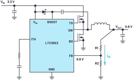

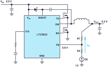
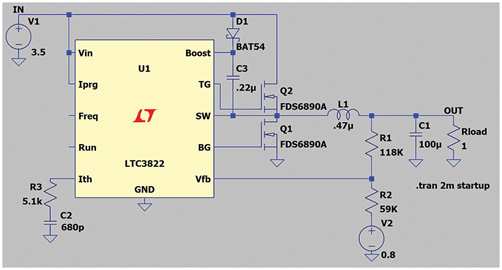
Figure 1. LTC3822 DC-DC Converter with Output Voltage of 0.6V or Higher
However, if a power supply voltage lower than 0.6 V is required, the circuit shown in Figure 1 needs to be adjusted, otherwise it cannot be used.
With some techniques, you can also make a switch or linear regulator produce a voltage lower than the feedback voltage. It can be realized by using the circuit shown in fig. 2. The resistance divider is connected to an external positive bias voltage to regulate the output voltage. This voltage can be generated by a low dropout regulator (LDO) or a reference voltage source. In this way, the resistance divider constitutes a voltage divider, and the current IFB flows in the opposite direction to the conventional situation in Figure 1. In Figure 2, current flows from an external reference voltage source to an output voltage via a resistive divider.
Formula 1 shows the relationship between the IC‘s feedback voltage (VFB), required output voltage (VOUT), applied positive DC bias voltage (VOFFSET), and resistance R1 and R2 of the resistance divider.
For the selection of resistance value of resistance divider, it is recommended that the sum of R1 and R2 should be between 100 k Ω and 500 k Ω. This makes the bias current low enough in power efficiency, but high enough to prevent excessive noise coupling to the sensitive feedback path.
Figure 2. Adjust the circuit in Figure 1 to produce an output voltage below 0.6 V
This design concept is generally applicable to generating a voltage lower than the lowest rated voltage of a switching regulator or linear regulator. However, it should be noted that the external reference voltage source should be started and operated before the DC-DC converter is turned on. If the auxiliary voltage is 0 V or has high resistance, the DC-DC converter may generate excessive voltage and damage the load circuit.
In the worst case, that is, when the switching regulator has not been turned on but the auxiliary voltage has been applied, the current IFB flowing through the resistance divider will charge the output capacitor to make its voltage higher than the set voltage. This occurs when the load has a very high impedance. Therefore, it may be necessary to set a minimum load to avoid this situation.
The accuracy of the auxiliary voltage (1V in Figure 2) of the resistance divider will directly affect the accuracy of the generated power supply voltage. Therefore, a particularly clean low ripple voltage should be used.
In addition, not all voltage converters are suitable for this operation. For example, the measuring range of the current detection amplifier in the DC-DC converter may only provide the operating range at a higher voltage. It should also be noted that a very low voltage is generated at a high input voltage and a low duty cycle is required. Here, it may be very helpful to select a switching regulator IC with a short minimum on time and work at a low switching frequency.
Figure 3. Simulation tools (such as LTspice of ADI) can be used ®) Perform an initial test of the circuit
If you want to run a linear regulator or a switching regulator at an output voltage lower than that specified by the IC manufacturer, it is very useful to use a simulation tool (such as the LTspice of ADI) to perform an initial check. Figure 3 shows a circuit composed of LTC3822, which uses an additional voltage source as the bias of the feedback path. In this circuit, a 200 mV output voltage is generated. According to the data book, LTC3822 is suitable for generating a minimum output voltage of 0.6 V. In the circuit, the auxiliary voltage source (voltage source V2 in Figure 3) can be realized by LDO regulator or reference voltage source. Using the techniques described in this paper, the circuit is completely tested, and even lower output voltage may be generated.
|
Disclaimer: This article is transferred from other platforms and does not represent the views and positions of this site. If there is any infringement or objection, please contact us to delete it. thank you! |


 Business consulting

 13823761625
 Mail me