


LDO capacitor selection guide
Time:2022-09-05
Views:1818
Why is the selection of capacitance important?
Capacitance is often neglected by people. The capacitor has neither billions of transistors nor the latest submicron manufacturing process. In the minds of many engineers, a capacitor is nothing more than two conductors plus an isolating electrolyte in the middle. All in all, they belong to one of the lowest level electronic components.
Engineers usually solve the noise problem by adding some capacitors. This is because they generally regard capacitance as a "panacea" to solve noise related problems, and rarely consider parameters other than capacitance and rated voltage. However, like other electronic components, capacitors also have defects, such as parasitic capacitance, inductance, capacitance temperature drift, voltage offset and other non ideal characteristics.
These factors must be considered when selecting capacitors for many bypass applications or applications where the actual capacitance of the capacitor is very important. Improper capacitor selection may lead to circuit instability, excessive noise or power consumption, shortened product life, and unpredictable circuit behavior.
Capacitance Technology
Capacitors have various sizes, rated voltages and other characteristics, which can meet the specific requirements of different applications. Common dielectric materials include oil, paper, glass, air, mica, various polymer films and metal oxides. Each electrolyte has a series of specific properties to meet the unique needs of each application.
In voltage regulators, there are three types of capacitors commonly used as voltage input and output bypass capacitors: multilayer ceramic capacitors, solid tantalum electrolytic capacitors and aluminum electrolytic capacitors.
Multilayer ceramic capacitor
Multilayer ceramic capacitor (MLCC) has the advantages of miniaturization, low effective series resistance and inductance (ESR and ESL) and wide operating temperature range. It is usually the first choice as a bypass capacitor.
It is not faultless. Depending on the dielectric material used, the capacitance may shift significantly with temperature changes and AC / DC bias. In addition, because dielectric materials are piezoelectric in many ceramic capacitors, vibration or mechanical shock may be converted into AC noise voltage on the capacitor. In most cases, this noise is generally in the microvolt range. However, in extreme cases, millivolt level noise may be generated.
Applications such as VCO, PLL, RF PA and low-level analog signal chain are very sensitive to noise on the power rail. This noise appears as phase noise in VCO and PLL, and carrier amplitude modulation in RFPA. In low-level signal chain applications such as EEG, ultrasound and CAT scan preamplifiers, noise will cause spurious noise in the output of these instruments. In all these noise sensitive applications, multilayer ceramic capacitors must be carefully evaluated.
It is very important to consider temperature and voltage effects when selecting ceramic capacitors. In the selection of multilayer ceramic capacitors, the process of determining the minimum capacitance of a capacitor according to the tolerance and DC bias characteristics is discussed.
Although ceramic capacitors still have shortcomings, they can achieve the smallest size and the most cost-effective solution for many applications, so they can be seen in almost every type of electronic equipment today.
Solid tantalum electrolytic capacitor
This capacitance has the highest capacitance per unit volume (CV product). Only double layer or super capacitor has higher CV product.
At 1 μ In the f range, ceramics are still smaller and ESR is lower than tantalum, but solid tantalum capacitors are unlikely to be affected by temperature, bias voltage or vibration effect. Tantalum is several times more expensive than ceramic capacitors, but tantalum is often the only viable choice in low-noise applications that cannot tolerate piezoelectric effects.
The traditional low value solid tantalum capacitors on the market usually use smaller housings, so the equivalent series resistance (ESR) is higher. Large capacity (> 68 μ F) Tantalum capacitors may have an ESR of less than 1 Ω, but are generally large in size.
Recently, a new tantalum capacitor appeared in the market, which uses conductive polymer electrolyte instead of ordinary manganese dioxide solid electrolyte. In the past, the surge current capacity of solid tantalum capacitors was limited, and a series resistor was required to limit the surge current to a safe value. Conductive polymer tantalum capacitors are not limited by surge current. Another advantage of this technology is that the capacitance ESR is lower.
The leakage current of any tantalum capacitor is several times larger than the equivalent ceramic capacitor, which may not be suitable for ultra-low current applications.
For example, at an operating temperature of 85 ° C, 1 μ The maximum leakage current of F / 25V tantalum capacitor under rated voltage is 2.5 μ A。
Many manufacturers provide 0805 shell, 1 μ F / 25V, 500m Ω ESR conductive polymer tantalum capacitor. Although the typical 1 μ F ceramic capacitance is larger, but the capacitance size of 0805 is significantly reduced in applications with low noise as the main design goal, such as RF and PLL.
Because the capacitance value of the solid tantalum capacitor can maintain stable capacitance characteristics with respect to temperature and bias voltage, the selection criteria only include tolerance, step-down within the operating temperature range and maximum ESR.
A major disadvantage of solid polymer electrolyte technology is that such tantalum capacitors are more susceptible to high temperatures in lead-free welding processes. In general, the manufacturer will specify that the capacitor shall not be exposed to more than three welding cycles. If this requirement is ignored in the assembly process, it will lead to long-term reliability problems.
Aluminum electrolytic capacitor
Traditional aluminum electrolytic capacitors often have large volume, high ESR and ESL, relatively high leakage current and limited service life (in thousands of hours).
OS-CON capacitor is a technology related to solid-state polymer tantalum capacitor. In fact, it came out 10 years or earlier than tantalum capacitor. They use organic semiconductor electrolyte and aluminum foil cathode to achieve lower ESR. Because there is no problem that the liquid electrolyte gradually dries out, the service life of OS-CON capacitor is much longer than that of traditional aluminum electrolytic capacitors.
At present, OS-CON capacitors on the market can withstand a high temperature of 125 ° C, but most of them still stay at 105 ° C.
Although the performance of OS-CON capacitors is significantly improved over traditional aluminum electrolytic capacitors, they tend to be larger and have higher ESR than ceramic capacitors or solid polymer tantalum capacitors. Like solid polymer tantalum capacitors, they are not affected by piezoelectricity and are suitable for applications requiring low noise.
Selection of multilayer ceramic capacitor
Output capacitance
The LDO design of ADI company uses small ceramic capacitors that save space to work, but as long as the ESR value is considered, most common capacitors can be used. The ESR of the output capacitance will affect the stability of the LDO control loop. In order to ensure the stable operation of LDO, it is recommended to use at least 1 μ F. ESR is a capacitance of 1 Ω or less.
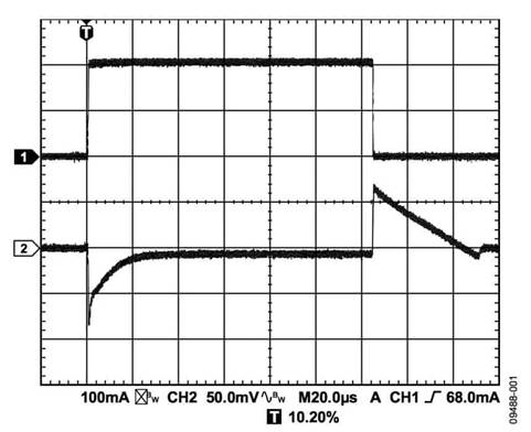
The output capacitance also affects the transient response of the load current change. Large output capacitance can improve the transient response of LDO to large load current changes. Figures 1 to 3 show that the output capacitance is 1 μ F、10 μ F and 20 μ The transient response of adp151 of F.
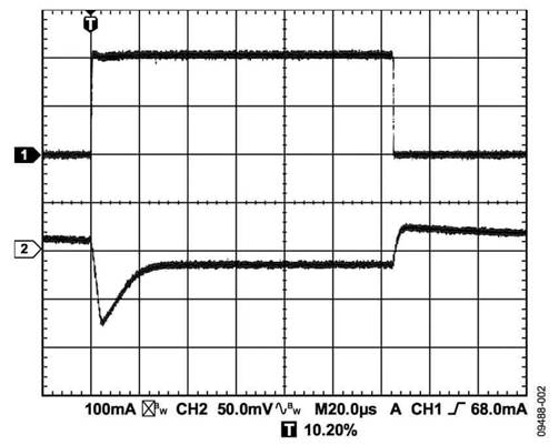
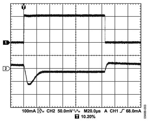
Because the bandwidth of the LDO control loop is limited, the output capacitance must provide most of the load current required for fast transients. one μ The f capacitor cannot supply current for a long time and generates a load transient of about 80 mV. ten μ The f capacitance reduces the load transient to about 70 MV. Increase the output capacitance to 20 μ F. The LDO control loop can capture and actively reduce load transients. Test conditions are shown in Table 1.

 In this example, the LDO specifies that the minimum output bypass capacitance within the desired operating voltage and temperature range is 0.70 μ F。 Therefore, the capacitance selected for this application meets this requirement.
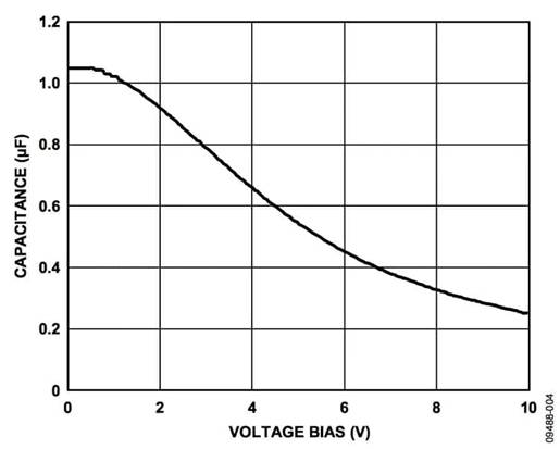
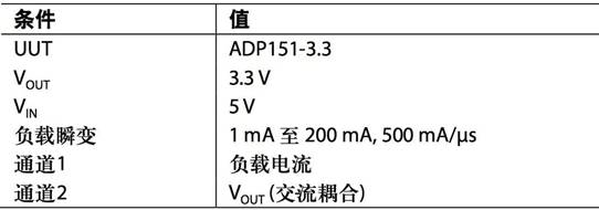
Table 1. Test conditions
Figure 1. Output load transient response, cout = 1 μ F
Figure 2. Output transient load response, cout = 10 μ F
Figure 3. Output load transient response, cout = 20 μ F
Input bypass capacitance
Connect a 1 between VIN and GND μ F capacitance can reduce the sensitivity of the circuit to PCB layout, especially in the case of long input traces or high source impedance. If the output capacitance is required to be greater than 1 μ F. Higher input capacitance shall be selected.
Input and output capacitance characteristics
As long as the minimum capacitance and maximum ESR requirements are met, LDO can use any capacitor with good quality. Ceramic capacitors can be made of a variety of dielectrics, and their characteristics are different due to different temperatures and applied voltages. The capacitor must have a dielectric sufficient to ensure minimum capacitance in the operating temperature range and DC bias conditions. X5R or X7R dielectrics with voltage ratings of 6.3V or 10V are recommended for 5V applications. Y5V and z5u dielectrics have poor temperature and DC bias characteristics, so they are not recommended to be used.
Figure 4 shows 0402 and 1 μ F. 10V, X5R capacitance and voltage bias characteristics. The voltage stability of a capacitor is greatly affected by the size of the capacitor package and the voltage rating. Generally speaking, capacitors with larger packages or higher voltage ratings have better voltage stability. The temperature change rate of X5R dielectric is ± 15% in the temperature range of - 40 ° C to + 85 ° C, which is not a function of package or voltage rating.
When considering the change of capacitance with temperature, element tolerance and voltage, the capacitance in the worst case can be determined by Formula 1.
Formula 1
Wherein:
Cbias is the effective capacitance at the operating voltage.
TVAR is the variation of capacitance with temperature in the worst case (a fraction).
TOL is the component tolerance in the worst case (a fraction).
In this example, it is assumed that the worst-case capacitance (TVAR) of X5R dielectric in the range of − 40 ° C to + 85 ° C is 0.15 (15%). Assuming a capacitance tolerance (TOL) of 0.10 (10%), cbias is 0.94 at 1.8 V μ F. As shown in Fig. 4.
By substituting these values into Formula 1:
Figure 4. Relationship between capacitance and voltage bias characteristics
Concluding remarks
In order to ensure the performance of LDO, it is necessary to understand and evaluate the influence of DC bias, temperature change and tolerance of bypass capacitor on the selected capacitor. In addition, in applications requiring low noise, low drift or high signal integrity, capacitor technology must also be seriously considered. All capacitors are affected by non ideal behavior, but some capacitor technologies are more suitable for certain specific applications than others.
|
Disclaimer: This article is transferred from other platforms and does not represent the views and positions of this site. If there is infringement or objection, please contact us to del |


 Business consulting

 13823761625
 Mail me