


DC-DC power conversion topology for Battery Energy Storage Systems (BESS)
Time:2024-05-28
Views:147
Source: ON Mei Author: On Mei
In recent years, the use of renewable energy sources such as solar energy has grown significantly. Factors driving this development include government incentives, technological advances, and reduced system costs. While photovoltaic (PV) systems are more reasonable than ever, there is still a major obstacle - solar doesn‘t produce energy when we need it most. Demand on the grid rises early in the morning, when people and businesses start their day; At night, when people return to their homes, demand on the grid also rises. However, solar power generation gradually increases after the sun rises, but it is still unable to provide energy during the period of high demand, such as after the sun goes down in the evening. As a result, renewable energy sources such as solar are increasingly integrated with energy storage systems to store energy for subsequent use.
Battery energy storage system (BESS) is usually used for energy storage systems that are compatible with solar photovoltaic power generation. Advances in BESS, such as better and cheaper batteries, are obvious, but less mentioned are the application of more efficient power conversion methods. Before diving into modern power conversion topologies, some important design considerations should be discussed.
Isolated and non-isolated
The isolated power conversion topology realizes electromagnetic isolation between the primary side and the secondary side by using transformers in the DC-DC phase. Therefore, the primary side and the secondary side have separate ground wires, rather than common ground. Due to the addition of transformers, isolated topologies are more expensive, bulkier and slightly less efficient, and current isolation is critical for safety reasons in grid-connected applications.
Bidirectional power conversion
The bidirectional topology reduces the number of power conversion modules required to connect low-voltage BESS to the corresponding high-voltage DC bus. onsemi‘s 25 kW fast DC EV charging pile reference design is an example of using two bidirectional power conversion modules. The bidirectional converter is connected to the power grid to charge the DC battery of the electric vehicle. The AC-DC conversion phase uses a three-phase 6-pack (6-pack) boosted active front end, while the DC-DC phase uses a dual active bridge (DAB) topology. The DC-DC dual active bridge is one of the more popular topologies, which will be discussed later.
Hard switch and soft switch
The traditional power converter adopts hard switch control scheme. The problem with hard switching is that when the transistor switches from the on state to the off state (and vice versa), the drain-to-source voltage (VDS) decreases and the drain current (ID) increases. There is an overlap between the two, and this overlap creates a power loss known as the on-off switch loss and the on-off switch loss. Soft switching is a control scheme for limiting switching losses by delaying ID ramp until VDS is close to zero. Delay the VDS ramp until ID is close to zero. This delay is called dead time, and the current/voltage ramp is called zero voltage (ZVS) and zero current switch (ZCS), respectively. Soft switching can be implemented with resonant switching topologies such as LLC and CLLC converters to significantly reduce switching losses.
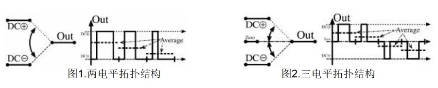
Two-level and three-level topology
The three-level converter topology is more advantageous than the two-level topology for several reasons. Firstly, the switching loss of the three-level topology is lower than that of the two-level topology. The switching loss is proportional to the square of the voltage applied to the switch (V2), and in a three-level topology only half of the total output voltage is borne by the (partial) switch. Other advantages come from lower current ripple and EMI. Similarly, only half of the total output voltage is applied to the boost inductor, which reduces the current ripple and makes it easier to filter. EMI is directly related to current ripple, and reducing current ripple reduces EMI. As the peak-to-peak switching voltage is reduced, dV/dt and dI/dt are also reduced, further reducing EMI.
Wide band gap technology
Wide band gap technologies such as silicon carbide (SiC) further improve the efficiency of the power conversion system. Due to the inherent properties of these devices, they offer many advantages over traditional silicon-based MOSFETs. Some of these important factors include: higher breakdown voltage of the device due to higher breakdown electric field and band gap energy; Higher thermal conductivity, which reduces cooling requirements; Lower on-resistance, resulting in improved on-loss; Higher electron saturation speeds enable faster switching speeds.
DC-DC topology
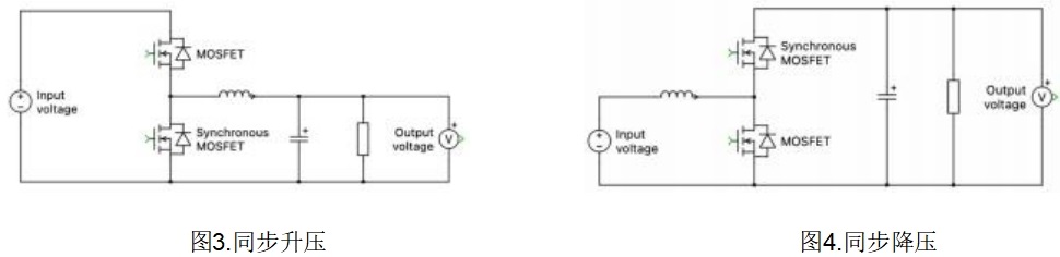
Synchronous buck, synchronous boost and flyback converters
Synchronous converters are derived from classic buck and boost converters. It is called a synchronous converter because it replaces the diode with an additional active switch. Flyback converters are similar to synchronous converters, except that isolation is added by replacing the inductor with a coupled inductor (also known as a 1:1 transformer). The addition of such a transformer can act as isolation, but a voltage clamp buffer circuit may be required to suppress the leakage current of the transformer. The cost of these converters is low due to the simple structure and modulation scheme, but losses and electromagnetic interference (EMI) tend to be higher compared to some more advanced topologies.
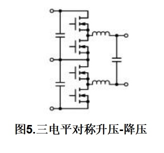
Symmetrical boost - buck
The symmetric buck-boost converter is an example of a three-level topology used in high power systems. As mentioned earlier, for standard two-level converters, the voltage stress on the switch comes from the total bus voltage, while for higher power systems, this value may reach 1000V or more. This requires the use of transistors rated at 1200V and above in high-power systems. In contrast, three-level topologies such as symmetric buck-boost converters use only devices with a rated voltage of half the bus voltage, and have the additional advantages of reduced switching losses, reduced electromagnetic interference (EMI), and smaller magnetic component volume. Its disadvantages mainly stem from the requirement for more switches and more complex control algorithms.
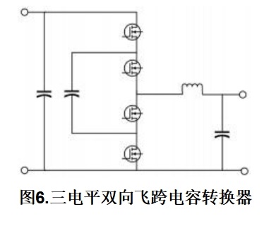
Flying transcapacitance Converter (FCC)
The flyover Capacitance converter (FCC) is a three-level converter that enables bidirectional power flow in this configuration. It consists of four switches, an inductor, and a flying capacitor that straddles two switches in the middle. Since this is a three-level topology, the flying span capacitor acts as a clamping capacitor (or constant voltage source), and the structure also has the advantage of halving the switching voltage stress. Therefore, the advantages of this topology include the use of lower voltages, higher performance switches, smaller passive components, and reduced electromagnetic interference. The disadvantage of this circuit topology is that it must be equipped with a starting circuit that regulates the voltage of the flying capacitor to half the voltage of the bus, thus taking full advantage of the low voltage switch.
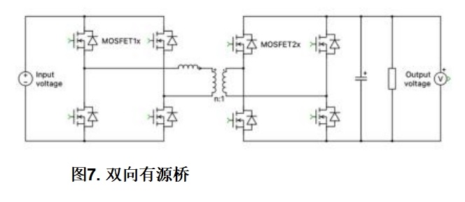
Dual Active Bridge (DAB)
Dual active bridge (DAB) is one of the most common isolated bidirectional topologies. As shown in Figure 7, it has a full bridge configuration on both the primary and secondary sides. Each bridge controls the direction of the power flow by phase shifting control, that is, by controlling square waves that are offset relative to each other. Some of the advantages of this topology include that the voltage stress on each switch is limited to the bus voltage, that the current stress on all switches on both sides is roughly equal, and that soft switching can be achieved without additional elements such as resonant circuits. Some disadvantages are due to high current ripple, the critical importance of the filter circuit, and the soft switching capability of the converter may fail under light load conditions.
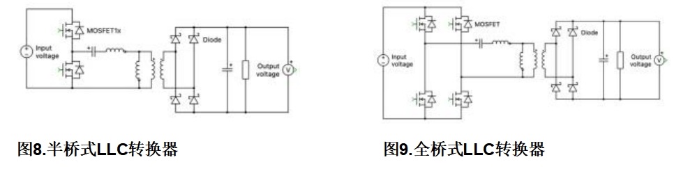
LLC Resonant Converter
The LLC converter is a resonant topology using soft switching technology. The figure below shows that this topology can be configured in a half-bridge or full-bridge configuration on the primary side. LLC converters typically operate in unidirectional mode, but can also operate bidirectional by replacing an existing diode with an active switch. The resonant loop of the circuit comprises a resonant inductor, a resonant capacitor and a magnetizing inductor. One advantage of this circuit over previous DAB topologies is that it maintains soft switching characteristics over the entire load range.
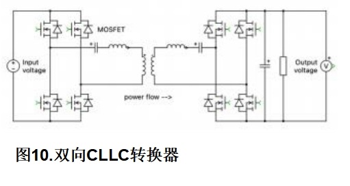
CLLC resonant converter
The CLLC converter is another resonant topology that can take advantage of soft switching technology and bidirectional power flow. It consists of a resonant inductor and a resonant capacitor on both the primary and secondary sides. A common advantage of this circuit and other circuits that include full Bridges on both the primary and secondary sides is that the control principle is the same. In addition, like the LLC converters before it, the CLLC enables soft switching over the entire load range. However, one reason CLLC is superior to LLC topology is the symmetric resonant loop. The LLC topology has asymmetric resonant loops that cause the reverse operation to be different from the forward operation. The CLLC with a symmetrical resonant loop solves this problem, making it easier to achieve bidirectional charging.
Sum up
The continued evolution of battery energy storage systems, along with the wider use of renewable energy generation technologies, has created the need for more efficient and reliable power conversion systems. This paper discusses the important features of modern power conversion systems and some common DC-DC circuit topologies that implement these features. Many of the circuit topologies discussed in this paper can be simulated using ON‘s free online PLECs-based Elite Power simulation tool to gain a deeper understanding of device - and system-level efficiencies. For more information, visit onsemi.cn for the latest updates on industry-leading design resources and innovative technologies for energy infrastructure applications.
|
Disclaimer: This article is transferred from other platforms and does not represent the views and positions of this site. If there is any infringement or objection, please contact us to delete it. thank you! |


 Business consulting

 13823761625
 Mail me