


Simulation fine-tuning: Improve the accuracy of power electronic circuits
Time:2024-05-19
Views:134
Source: ON Beauty Author: James Victory
In the field of power electronics and circuit simulation, precision is critical. The authenticity of the simulation results depends on the accuracy of the models used by each device. Whether it is IGBTs, silicon carbide (SiC) or silicon MOSFETs, the reliability of simulation predictions is closely related to the accuracy of the model. As the old saying goes, "garbage in, garbage out", if the input is garbage, then the output is garbage.
Designers build system-level models based on device characteristics (such as conduction loss, energy loss, and thermal resistance) measured in the product manual in a laboratory environment, and most industry standard models do the same. However, these models based on product manuals are the product of laboratory configurations and environments and do not always reflect the conditions encountered in practice. Therefore, it cannot be taken for granted that these models from product manuals accurately reflect the complex parasitic environments faced by power electronics designers. In fact, the probability that the manufacturer‘s experimental environment is exactly the same as the power electronics designer‘s application environment is close to zero. The obvious difference between the experimental environment and the application environment can lead to significant errors in the simulation results in practical applications, and the error rate is often as high as 20-30% or more. To solve this problem, current practices must be improved wherever possible.
onsemi‘s PLECS Model Self Generation Tool (SSPMG) is groundbreaking, allowing users to create customized PLECS models by entering specific parasitic environments. An off-the-shelf suit, for example, is unlikely to fit perfectly, whereas the SSPMG is like an advanced tailor who tailors your clothes and can accurately tailor the model to the specific application.
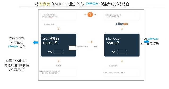
Figure 1: Elite Power Simulation tool and PLECS model self-generation tool
The core idea behind the SSPMG approach is simple. The focus is not on the results measured by On Beauty in the laboratory, but on the specific application in your environment. Users can fine-tune the model according to their respective environment, which in turn can significantly improve the accuracy of the simulation. This emphasis on customization and accuracy is not just a theoretical concept, but is translated into concrete solutions that can yield tangible results. The industry has come to realize that there are obvious limitations to generic models, and that there is great potential for customizing simulations for different needs.
On‘s SSPMG simulation tool also enables users to customize data-intensive parameter tables based on electrical bias and temperature conditions. The goal is to ensure accurate interpolation between data points in the table and minimize the need for extrapolations, which often introduce errors into system simulations.
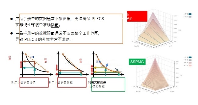
Figure 2: One of the characteristics of SSPMG: Data intensive loss parameter table
The SSPMG tool developed by On contains "boundary models" that represent different manufacturing conditions for electronics. Among them, the threshold voltage, RDSon, breakdown voltage, capacitance and other parameters will vary depending on the physical characteristics of the fab. This can significantly affect the energy loss, on-loss, and temperature behavior of the device under test, making it important to capture these associated parameter differences, especially at the system level.
To this end, ON introduced a PLECS model for hard and soft switches, in addition to synchronous rectification operations, and only for master switch operations. The PLECS tool can simulate a variety of soft switching applications, including DC-DC LLC and CLLC resonances, dual active Bridges, and phase-shifted full bridge topologies.
Soft switch and hard switch
In the field of power electronics, it is important to make a clear distinction between soft and hard switches. For hard switches, double pulse testing (DPT) is used to accurately calculate losses. However, the performance of the soft switch is greatly affected by the topology and working mode, so the dual pulse test can not accurately calculate the specific loss.
To address this problem, SSPMG uses a new conversion loss tester to accurately calculate energy losses for a range of topologies, including phase-shifted full Bridges, DC-DC LLC, and CLLC resonant topologies. This approach specifically designed for soft switching improves the accuracy of soft switching models that are often overlooked by the industry. In this way, engineers can obtain an accurate representation of the design solution, thereby avoiding errors caused by incompatible simulation conditions. Thanks to our integrated capabilities, designers are able to use accurate models regardless of the switching topology, thus ensuring the accuracy of the simulation.
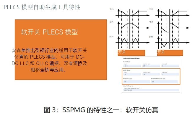
Figure 3: One of the features of SSPMG: soft-switch simulation
Switching loss test
DPT is a common method for measuring the switching loss of semiconductor devices. The specific steps used in this method include: first, the inductive current is induced by activating the low-side switch, and then the turn-off loss of the low-side switch when it is turned off at a certain current point is measured. The inductive current continues to be maintained by the high-side diode and can be considered constant due to the low voltage drop and short duration. Finally, the low-side switch is switched on again, so the on-off loss can be measured using an inductive current similar to that used during the off period.
Whether a half-bridge or a quarter-bridge is used in the setup will affect the switching loss, mainly because of the characteristic difference between the SiC Schottky diode and the MOSFET body diode. This configuration, called a "boost" type tester, affects the main switching loss because the reverse recovery current in the high-side switch/diode affects the low-side switching loss at on-off.
External factors such as parasitic capacitance and PCB leakage of inductors can significantly affect the loss of active switching. The parasitic capacitance of the inductor will affect Eon and Eoff, thus affecting the overall loss. In addition, devices such as PCB leakage sensing and ferrite beads used to mitigate EMI can change the size and performance of the switching loop, slowing the current climb and allowing the voltage to reach lower levels, thus affecting losses.
The DPT double pulse tester can effectively measure losses and even provide high precision assurance for circuits with very little parasitic component influence. While ON‘s advanced dual-pulse testers do an excellent job of comparing combination factors such as chip size and package, it is important to note that the losses in the test environment may not match those in real-world application scenarios. The specific parasitic components used by the user can greatly affect the actual losses, so it is impractical to customize new Settings for each design.
Model-based simulation can replace this resource-intensive, limited, and complex approach based on measurement. Using parametric simulation and highly accurate simulation models, such as On‘s Physically scalable SPICE model, power electronics designers are able to quickly generate accurate loss models. These simulations enable the evaluation of multiple scenarios in a single run, providing valuable information more quickly and cost-effectively than laborious measurement techniques.
With more than 30 parameters, On‘s SSPMG can fine-tune a simulation schematic for a dual pulse or conversion loss tester to extract discrete and power module losses for SiC MOSFETs. This comprehensive tool integrates multiple application phases and scenarios, and enables modification of gate drive voltages, so power electronics designers can efficiently generate highly accurate PLECS loss models for specific applications.
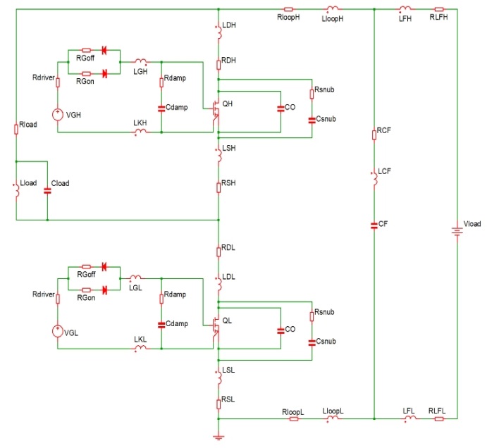
Figure 4: Basic schematic diagram of dual pulse tester
Case study - DC fast charging pile
Elite Power Simulation tools and SSPMG have excellent features that can significantly reduce product development cycles, especially in areas where design timelines need to be optimized, such as DC Fast charging (DCFC). 25 kW DC fast charging is an important part of electric vehicle charging infrastructure, where tool deployment is a typical example. In this case, the simulation tool effectively promotes the comparative study of the first-generation and third-generation silicon carbide half-bridge modules, and accurately predicts the efficiency difference between them, which is in good agreement with the experimental results.
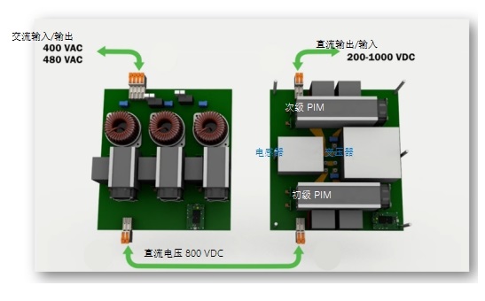
Figure 5: System board: PFC + DC-DC mechanical sketch
On analyzed and compared the measured data and simulation results of 25kW DC fast charge. Although there is a small deviation between the simulation and the actual measured total module losses, it shows a good correlation. The SSPMG derived model incorporates complex details such as layout parasitic effects and motor winding capacitance to improve the accuracy of simulation results, helping Elite Power simulation tools provide deeper analysis.
Various filters, amplifiers, and gate drivers interwoven with SiC MOSFETs form the internal architecture of the charging pile. By utilizing different modules and topologies, the intricate interactions between AC-DC active converters and DC-DC converters are clarified to achieve the desired performance. The evaluation showed that the loss curve fluctuated in the ±10% range, but the simulation gave a complex loss curve with a fluctuation of ±5%.
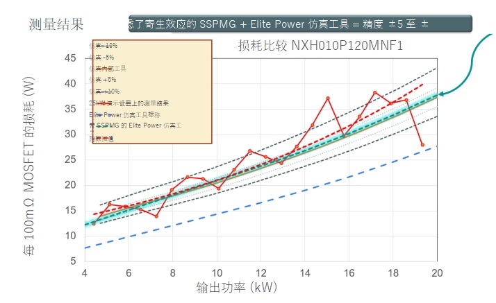
Figure 6: Measurement results
The dynamic interaction between simulation and observation data shows that accurate modeling and detailed measurements are critical to evaluating the performance of power electronic devices.
New situation
Elite Power simulation tools and SSPMG can be adapted to a wide range of semiconductor technologies. Both tools were initially focused on SiC products, but have recently expanded to include 7th generation (FS7) IGBT products. Both tools are versatile, and engineers can flexibly apply them to different devices to customize simulations according to specific requirements.
About the author
James Victory is a research fellow at ON Technologies, specializing in power modeling and simulation. In June 2008, he co-founded Sentinel IC Technologies, a company dedicated to providing professional design services in RF analog and power technology. Prior to that, he served as Executive Director of Design Support at Jazz Semiconductor. He began his career at MOTOROLA in 1992, primarily modeling semiconductor devices in the areas of RF simulation and power technology. He received his B.S., M.S. and Ph.D. degrees in Electrical Engineering from Arizona State University in 1990, 1992 and 1994, respectively. He has published more than 50 articles, including guest papers and seminar tutorials, and holds six patents related to semiconductor device modeling and simulation.
|
Disclaimer: This article is transferred from other platforms and does not represent the views and positions of this site. If there is any infringement or objection, please contact us to delete it. thank you! |


 Business consulting

 13823761625
 Mail me