


Dailian Dayoushang Group launched a 7KW on-board charger solution based on ST products
Time:2024-05-10
Views:151
Source: General Assembly Author: General Assembly
On April 23, 2024, the leading international distributor of semiconductor components in the Asia Pacific market, DDA Holdings, announced that its Yousun unit launched a 7KW on-board charger solution based on ST‘s STDES-7KWOBC development board.

Figure 1- The display board of the 7KW on-board charger solution based on ST products
With the increasing awareness of environmental protection and the rapid development of new energy vehicle technology, the penetration rate of electric vehicles (EV) has been rising year by year, and has become an important direction for the development of the automobile industry. Among them, the on-board charger (OBC) is the core component of the electric vehicle charging system, and its performance and efficiency are directly related to the charging experience and convenience of electric vehicles. In order to simplify the design of on-board chargers, the company launched a 7KW on-board chargers solution based on the STDES-7KWOBC development board, which can charge electric vehicles through home AC power plugs or public AC charging stations.

Figure 2- The scenario application diagram of the 7KW on-board charger solution based on ST products
The scheme is embedded with single-phase staggered totem pole PFC with SiC and dual electrical isolation full bridge LLC DC-DC ZVS resonant converter. In the PFC circuit part, the scheme adopts TN3050H-12GY-TR, STBR3012G2Y, SCTH35N65G2V-7AG and STGAP1AS devices. The circuit part of LLC adopts STB47N60DM6AG, STPSC20065GY-TR, A6387 and other components. In terms of circuit control, both PFC circuit and LLC circuit are controlled by SPC58NN84E7 MCU. STDES-7KWOBC staggered totem pole PFC switching frequency 70KHz, with inductive current balance control function. The dual DC-DC LLC resonant converters have output current balance control functions in the range of 80KHz to 310KHz, which ensure current balance in the parallel stage.
The power platform for this solution is a 7KW module capable of providing either constant current (CC) or constant voltage (CV) at the output. It is worth mentioning that the lower insulated metal substrate (IMS) on the aluminum substrate greatly improves the heat dissipation efficiency and supports forced air or liquid cooling methods. The design between each sub-system module allows for easy bus connections via wires, simplifying the design process. In addition, the solution uses SiC MOS/Diode, which enables the system to achieve high output power and higher power density.
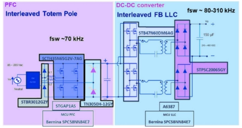
Figure 3- Block diagram of the 7KW on-board charger solution based on ST products
With SiC and SJ power MOSFETs, silicon and SiC diodes, gate drivers, SPC58NN84E7 microcontrollers, and SCR thyristors for inrush current limitation, the solution delivers high efficiency and high power density. Not only that, each module of the solution can be easily interconnected by wire or bus, which not only simplifies the connection process, but also helps to achieve higher output power.
Core technical advantages:
Bus interconnection;
Vehicle-level MCU control;
The total peak efficiency is greater than 94%;
Short circuit, overload, overheat protection;
Compatible with different types of batteries and different types of input power supplies;
It is stable under different voltage and current conditions to ensure the normal charging process.
Project specification:
The front-end PFC stage adopts a 2-channel staggered totem pole topology, and the operating frequency is 70KHz.
Digital inrush current control;
The DC-DC stage adopts FB LLC resonant topology, and the resonant frequency is 140KHz.
Constant current and constant pressure mode;
Control level based on SPC58NN84E7 MCU;
12V input power supply voltage and output voltage GND (high voltage battery) electrical isolation;
Possibility of bus interconnection;
Power factor correction stage:
Main products: TN3050H-12GY-TR SCR, STBR3012G2Y bypass diode, SCTH35N65G2V-7AG silicon carbide power field effect transistor;
Input: 85V to 265V AC, 45Hz to 65Hz;
Digital surge current limiter;
Maximum input current: 32A RMS value;
Switching frequency: 70KHz;
Average current mode control in continuous on-mode (CCM);
PID or 2p2z 2x independent current loop regulator;
PID or 2p2pz voltage regulator;
SPC58NN84E7 MCU controller.
DC-DC class:
Main products: STB47N60DM6AG power field effect transistor, STPSC20065GY-TR output diode, A6387 gate driver;
Output voltage: 250V to 450V DC;
Switching frequency: 92KHZ to 250KHz, starting frequency is 350KHz;
Two independent current loops (CC);
A voltage loop plus current balance (CV);
PID regulator;
SPC58NN84E7 MCU controller.
Comply with RoHs standards.
|
Disclaimer: This article is transferred from other platforms and does not represent the views and positions of this site. If there is any infringement or objection, please contact us to delete it. thank you! |


 Business consulting

 13823761625
 Mail me